
|
1. 方案介绍 系统功能就是一个可以通过手机蓝牙实时查看远端采集器实时温度的系统。系统由采集器和Android手机端组成。采集器由STM32F072-Nucleo、蓝牙转串口模块(信弛达BM-S02模块)、温度传感器(MCP9808)组成。Android手机端负责和蓝牙模块通信,获取温度数据,并显示。 2. 主要功能 系统重点除了完成一个特定的功能外,另一个目的在于研究CubeMX开发平台和RTOS,完成一系列通用的软件模块。已经完成了一些比较有用的模块,可供网友参考、指正。开发环境基于STM32 CubeMX+FreeRTOS(实际上是CMSIS OS的接口),所有的API调用都是基于CubeMX生成的Hal层API。完成的软件模块包括: 基于uart2和FreeROTS-cli的命令终端,支持上下翻页和命令自动补全); 基于DMA的串口驱动,适合和需要大吞吐的wifi或蓝牙模块通信的场合; 以及一个简单的MCP9808的驱动(CubeMX hal的i2c接口先赞一个)。 3. 实施方案现场实施 
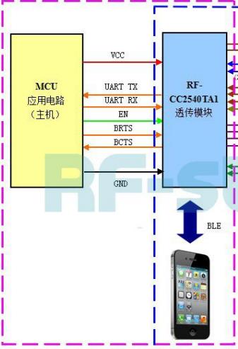
蓝牙部分原理(出自官方文档) 
BRTS、BCTS、GND接地,UART_TX、UART_RX接Nucleo的UART1_TX(PA9)和UART1_RX(PA10),VCC接3.3V。MCP9808原理图 
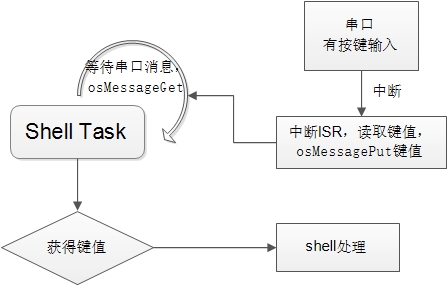
MCP9808地址可编程,上下拉都接了,实际贴片时会根据需要决定是否贴上电阻,这样可以在一个i2c总线上挂多个MCP9808。 4. 软件实现 printf到串口 重载fputc函数 #define PRINT_BUF_SIZE 2 static int read_bc = 0; static int __serial_send(char *buf, uint16_t size) { HAL_UART_Transmit(&huart2, (uint8_t *)buf, size, 100); return size; } int fputc(int ch, FILE *f) { /* Place your implementation of fputc here */ /* e.g. write a character to the USART */ char buf[PRINT_BUF_SIZE]; buf[0] = ch; if (ch == '\r') { read_bc = 1; } else if (ch == '\n') { if (!read_bc) { buf[1] = '\r'; __serial_send(buf, 2); return ch; } read_bc = 0; } else if (read_bc) { read_bc = 0; } __serial_send(buf, 1); return ch; } 命令终端 基于uart2和FreeRTOS-Cli实现,由于Nucleo的虚拟串口直接和uart2是相通的,因此不需要再另接串口线。 总体流程 
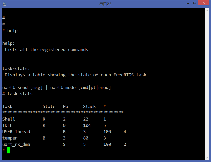
代码逻辑并不复杂,要讲有点麻烦,会把所有代码发出来,参考shell.c代码。 为了命令补全,在FreeRTOS-Cli中加了一个函数,其余FreeRTOS-Cli代码未做修改。 实际效果如图所示: 
显示不对齐是由于FreeRTOS的vTaskList函数实现导致,不影响调试。 UART DMA传输 主要用于大流量的数据通信,比如:wifi、蓝牙模块和MCU之间的通信。 网上有很多关于串口DMA的讨论,主要集中在UART DMA收上面,因为DMA接受需要固定长度的字节数,而这个限制对大部分应用是不可能做到的。所以,有人讨论了用有通信格式的数据包的方式,这个其实也不能完全满足所有需要,比如:这里用的蓝牙模块有的时候会打印一些系统信息,有的时候是远端传过来的数据,不太好区分。 这里的DMA传输无需格式,无需固定长度,实现方式参考了这个帖子http://blog.csdn.net/jdh99/article/details/8444474,现在STM32F103上调通,后来移到Nucleo平台,主要困难在于CubeMX的API比较生疏,研究完具体实现才能明白怎么做。核心在于先启动DMA RX传输,然后在IT_IDLE中断中处理接受的数据包(不完整的DMA RX接收,但一次通信已结束)。 初始化 typedef struct { uint8_t *rxbuf; uint8_t *txbuf; uint16_t rxbuf_size; uint16_t txbuf_size; uint32_t flag; osSemaphoreId rx_semp_id, tx_semp_id; UART_HandleTypeDef *UART_hd; //DMA_HandleTypeDef *DMARx_hd, *DMATx_hd; serial_rx_callback rx; int rxlen; } uart_dma_info_t; int uart_dma_init(UART_HandleTypeDef *UART_hd, serial_rx_callback rx, uint16_t rxbuf_size, uint16_t txbuf_size) { int id; uart_dma_info_t *info; osSemaphoreDef(uart_rx_sep); osSemaphoreDef(uart_tx_sep); osThreadDef(uart_rx_dma, uartRxTask, osPriorityHigh, 0, configMINIMAL_STACK_SIZE+100); assert_param(UART_hd != NULL); id = __get_uart_id(UART_hd->Instance); assert_param(id >= 0 && id < MAX_UART_NUM); info = &uart_info[id]; info->rxbuf_size = rxbuf_size; info->txbuf_size = txbuf_size; info->UART_hd = UART_hd; info->rx = rx; if (rxbuf_size > 0) { assert_param(info->UART_hd->hdmarx); info->rxbuf = pvPortMalloc(rxbuf_size); assert_param(info->rxbuf); osThreadCreate (osThread(uart_rx_dma), info); info->rx_semp_id = osSemaphoreCreate(osSemaphore(uart_rx_sep), 1); assert_param(info->rx_semp_id); osSemaphoreWait(info->rx_semp_id, osWaitForever);//skip the first time __HAL_UART_DISABLE(info->UART_hd); info->UART_hd->Instance->CR3 |= UART_DMA_RX_ENABLE; __HAL_UART_ENABLE(info->UART_hd); HAL_DMA_Start(info->UART_hd->hdmarx, (uint32_t)&info->UART_hd->Instance->RDR, (uint32_t)info->rxbuf, info->rxbuf_size); } if (txbuf_size > 0) { assert_param(info->UART_hd->hdmatx); info->txbuf = pvPortMalloc(txbuf_size); assert_param(info->txbuf); info->tx_semp_id = osSemaphoreCreate(osSemaphore(uart_tx_sep), 1); assert_param(info->tx_semp_id); osSemaphoreWait(info->tx_semp_id, osWaitForever);// skip the first wait info->UART_hd->hdmatx->XferCpltCallback = uart_dma_send_finsh_cb; info->UART_hd->hdmatx->XferErrorCallback = uart_dma_send_err_cb; info->UART_hd->Instance->CR3 |= UART_DMA_TX_ENABLE; } return id; } 中断处理 void USART1_IRQHandler(void) { /* USER CODE BEGIN USART1_IRQn 0 */ /* USER CODE END USART1_IRQn 0 */ HAL_UART_IRQHandler(&huart1); /* USER CODE BEGIN USART1_IRQn 1 */ if (__HAL_UART_GET_IT(&huart1, UART_IT_IDLE) != RESET) { uart_dma_recv_isr(uart1_fd); } /* USER CODE END USART1_IRQn 1 */ } void uart_dma_recv_isr(int fd) { uart_dma_info_t *info; uint32_t temp = 0; assert_param(fd >= 0 && fd < MAX_UART_NUM); info = &uart_info[fd]; assert_param(info->UART_hd->hdmarx); __HAL_UART_CLEAR_IT(info->UART_hd, UART_CLEAR_IDLEF); SET_BIT(info->UART_hd->hdmarx->ErrorCode, HAL_DMA_ERROR_NONE); /* Change the DMA state */ info->UART_hd->hdmarx->State = HAL_DMA_STATE_READY; /* Process Unlocked */ __HAL_UNLOCK(info->UART_hd->hdmarx); __HAL_DMA_DISABLE(info->UART_hd->hdmarx); temp = info->rxbuf_size - info->UART_hd->hdmarx->Instance->CNDTR; if (temp > 0) { info->rxlen = temp; osSemaphoreRelease(info->rx_semp_id); } HAL_DMA_Start(info->UART_hd->hdmarx, (uint32_t)&info->UART_hd->Instance->RDR, (uint32_t)info->rxbuf, info->rxbuf_size); } 接收处理线程 static void uartRxTask(void const *args) { uart_dma_info_t *info = (uart_dma_info_t *)args; while (1) { osSemaphoreWait(info->rx_semp_id, osWaitForever); if (info->rx && info->rxlen > 0) { info->rx(info->rxbuf, info->rxlen); } } } 具体实现看附件把,贴代码也不太容易说清楚。 MCP9808驱动 做了一些封装,但基本上只要调用HAL_I2C_Mem_Read就可以搞定了。 MCU全部的代码见附件  f0fmw.zip
(6.88 MB, 下载次数: 2620)
|
 微信公众号
微信公众号
 手机版
手机版

嗯,其实这个东西主要是前端和后端难搞,前端指探头部分,如果就是用i2c芯片读读,确实没什么难度,但要是精度高,并且探头要非常小,这个难度一下子就大起来了,像这类的要求在实验室设备上要求比较多。如果是民用,重点还是app要搞好,单片机这里比较简单。
这次的东西其实硬件和功能都比较简单,重点还是研究基于STM32CubeMX的开发,现在毕竟文档和案例都比较少,弄个这个给大家参考参考。