|
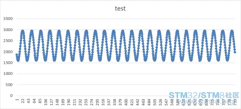
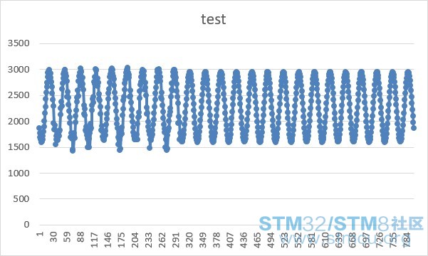
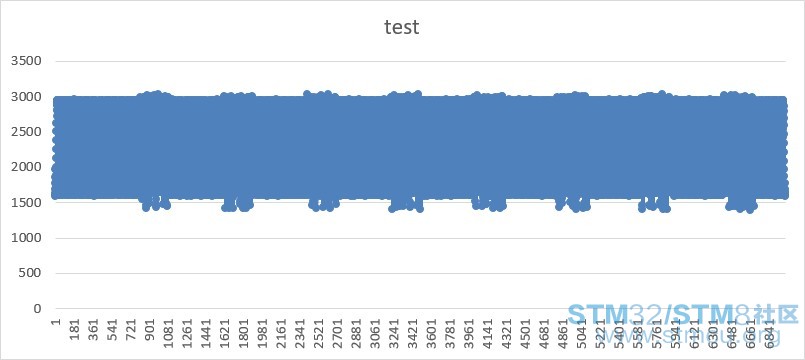
使用的晶片為STM32L152 編寫程式內容大略為: ADC轉換→ADC_DR暫存→藉由DMA搬運到自訂的陣列中 →經由USART在PC端印出 (其中ADC藉由TIM3外部觸發,每儲存N筆轉換後進入DMA中斷並匯入資料) 附上程式碼 main.c /* Includes ------------------------------------------------------------------*/ #include "stm32l1xx.h" #include <stdio.h> /* Private typedef -----------------------------------------------------------*/ /* Private define ------------------------------------------------------------*/ #define ADC1_DR_ADDRESS ((uint32_t)0x40012458) /* Private macro -------------------------------------------------------------*/ /* Private variables ---------------------------------------------------------*/ volatile uint16_t ADC_values[ARRAYSIZE]; volatile uint8_t bufferIndex; int32_t a=0; __IO extern int16_t adcInt_O[800][2]; __IO extern int16_t adcInt_S[800][2]; __IO extern int16_t storetime; __IO extern int8_t Flag; int16_t adcInt_Buffer_O[800]; int16_t adcInt_Buffer_S[; /* Private function prototypes -----------------------------------------------*/ void ADC_Configuration(void); void DMA_Configuration(void); void USART_Configuration(void); void RCC_Configuration(void); void NVIC_Configuration(void); void TIM3_Configuration(void); int main(void) { Flag =0; RCC_Configuration(); TIM3_Configuration(); ADC_Configuration(); DMA_Configuration(); USART_Configuration(); while(1) { if(Flag ==1) /*匯入資料*/ { Flag = 0; for(a=0; a<800; a++ ) /*怕資料被覆蓋*/ { adcInt_Buffer_O[a]=adcInt_O[a][(bufferIndex-1) & 0x1]; adcInt_Buffer_S[a]=adcInt_S[a][(bufferIndex-1) & 0x1]; } for(a=0 ; a<800 ; a++) { printf("%d\r\n", adcInt_Buffer_O[a]); } } } } /* ADC1 channel18 configuration using DMA1 channel1 */ void ADC_Configuration(void) { /*----------------- ADC1 configuration with DMA enabled --------------------*/ GPIO_InitTypeDef GPIO_InitStructure; ADC_InitTypeDef ADC_InitStructure; /* Enable ADC1 clock */ RCC_APB2PeriphClockCmd(RCC_APB2Periph_ADC1, ENABLE); RCC_AHBPeriphClockCmd(RCC_AHBPeriph_GPIOB, ENABLE); /* Configure PB.12 (ADC Channel18) in analog mode */ GPIO_StructInit(&GPIO_InitStructure); GPIO_InitStructure.GPIO_Pin = GPIO_Pin_12; GPIO_InitStructure.GPIO_Mode = GPIO_Mode_AN; GPIO_InitStructure.GPIO_PuPd = GPIO_PuPd_NOPULL; GPIO_Init(GPIOB, &GPIO_InitStructure); /* Configure PB.13 (ADC Channel19) in analog mode */ GPIO_StructInit(&GPIO_InitStructure); GPIO_InitStructure.GPIO_Pin = GPIO_Pin_13; GPIO_InitStructure.GPIO_Mode = GPIO_Mode_AN; GPIO_InitStructure.GPIO_PuPd = GPIO_PuPd_NOPULL; GPIO_Init(GPIOB, &GPIO_InitStructure); /* ADC1 configuration */ ADC_InitStructure.ADC_Resolution = ADC_Resolution_12b; ADC_InitStructure.ADC_ScanConvMode = ENABLE; ADC_InitStructure.ADC_ContinuousConvMode = DISABLE; ADC_InitStructure.ADC_ExternalTrigConvEdge=ADC_ExternalTrigConvEdge_Rising; ADC_InitStructure.ADC_ExternalTrigConv=ADC_ExternalTrigConv_T3_CC1; ADC_InitStructure.ADC_DataAlign = ADC_DataAlign_Right; ADC_InitStructure.ADC_NbrOfConversion = 2; /*雙通道採集*/ ADC_Init(ADC1, &ADC_InitStructure); /* ADC1 regular channel18 configuration */ ADC_RegularChannelConfig(ADC1, ADC_Channel_18, 1, ADC_SampleTime_384Cycles); ADC_RegularChannelConfig(ADC1, ADC_Channel_19, 2, ADC_SampleTime_384Cycles); /* Enable the request after last transfer for DMA Circular mode */ ADC_DMARequestAfterLastTransferCmd(ADC1, ENABLE); /* Enable ADC1 */ ADC_Cmd(ADC1, ENABLE); /* Enable ADC1 DMA */ ADC_DMACmd(ADC1, ENABLE); } void DMA_Configuration(void) { /*------------------------ DMA1 configuration ------------------------------*/ DMA_InitTypeDef DMA_InitStructure; NVIC_InitTypeDef NVIC_InitStructure; /* Enable DMA1 clock */ RCC_AHBPeriphClockCmd(RCC_AHBPeriph_DMA1, ENABLE); /* DMA1 channel1 configuration */ DMA_DeInit(DMA1_Channel1); DMA_InitStructure.DMA_M2M = DMA_M2M_Disable; DMA_InitStructure.DMA_Mode = DMA_Mode_Circular; DMA_InitStructure.DMA_Priority = DMA_Priority_High; DMA_InitStructure.DMA_PeripheralDataSize = DMA_PeripheralDataSize_HalfWord; DMA_InitStructure.DMA_MemoryDataSize = DMA_MemoryDataSize_HalfWord; DMA_InitStructure.DMA_PeripheralInc = DMA_PeripheralInc_Disable; DMA_InitStructure.DMA_MemoryInc = DMA_MemoryInc_Enable; DMA_InitStructure.DMA_DIR = DMA_DIR_PeripheralSRC; DMA_InitStructure.DMA_BufferSize = ARRAYSIZE; DMA_InitStructure.DMA_PeripheralBaseAddr = (uint32_t)ADC1_DR_ADDRESS; DMA_InitStructure.DMA_MemoryBaseAddr = (uint32_t)ADC_values; DMA_Init(DMA1_Channel1, &DMA_InitStructure); DMA_ITConfig(DMA1_Channel1, DMA_IT_TC, ENABLE); /* Enable DMA1 channel1 */ DMA_Cmd(DMA1_Channel1, ENABLE); /*Enable DMA1 channel IRQ Channel */ NVIC_InitStructure.NVIC_IRQChannel = DMA1_Channel1_IRQn; NVIC_InitStructure.NVIC_IRQChannelPreemptionPriority = 1; NVIC_InitStructure.NVIC_IRQChannelSubPriority = 0; NVIC_InitStructure.NVIC_IRQChannelCmd = ENABLE; NVIC_Init(&NVIC_InitStructure); } void USART_Configuration(void) { USART_InitTypeDef USART_InitStructure; GPIO_InitTypeDef GPIO_InitStructure; RCC_AHBPeriphClockCmd(RCC_AHBPeriph_GPIOA, ENABLE); RCC_APB1PeriphClockCmd(RCC_APB1Periph_USART2, ENABLE); GPIO_PinAFConfig(GPIOA, GPIO_PinSource2, GPIO_AF_USART2); GPIO_PinAFConfig(GPIOA, GPIO_PinSource3, GPIO_AF_USART2); GPIO_InitStructure.GPIO_OType = GPIO_OType_PP; GPIO_InitStructure.GPIO_PuPd = GPIO_PuPd_UP; GPIO_InitStructure.GPIO_Mode = GPIO_Mode_AF; GPIO_InitStructure.GPIO_Pin = GPIO_Pin_2; GPIO_InitStructure.GPIO_Speed = GPIO_Speed_40MHz; GPIO_Init(GPIOA, &GPIO_InitStructure); GPIO_InitStructure.GPIO_Mode = GPIO_Mode_AF; GPIO_InitStructure.GPIO_Pin = GPIO_Pin_3; GPIO_Init(GPIOA, &GPIO_InitStructure); USART_InitStructure.USART_BaudRate = 115200; USART_InitStructure.USART_WordLength = USART_WordLength_8b; USART_InitStructure.USART_StopBits = USART_StopBits_1; USART_InitStructure.USART_Parity = USART_Parity_No; USART_InitStructure.USART_HardwareFlowControl = USART_HardwareFlowControl_RTS; USART_InitStructure.USART_Mode = USART_Mode_Rx | USART_Mode_Tx; USART_Init(USART2, &USART_InitStructure); USART_Cmd(USART2, ENABLE); } void RCC_Configuration(void) { /* Enable HSI Clock */ RCC_HSICmd(ENABLE); /*!< Wait till HSI is ready */ while (RCC_GetFlagStatus(RCC_FLAG_HSIRDY) == RESET); /* Set HSI as sys clock*/ RCC_SYSCLKConfig(RCC_SYSCLKSource_HSI); /* Set MSI clock range to ~4.194MHz*/ RCC_MSIRangeConfig(RCC_MSIRange_6); /* Enable the GPIOs clocks */ RCC_AHBPeriphClockCmd(RCC_AHBPeriph_GPIOA | RCC_AHBPeriph_GPIOB | RCC_AHBPeriph_GPIOC| RCC_AHBPeriph_GPIOD| RCC_AHBPeriph_GPIOE| RCC_AHBPeriph_GPIOH, ENABLE); /* Enable comparator, LCD and PWR mngt clocks */ RCC_APB1PeriphClockCmd(RCC_APB1Periph_COMP | RCC_APB1Periph_LCD | RCC_APB1Periph_PWR,ENABLE); /* Enable ADC & SYSCFG clocks */ RCC_APB2PeriphClockCmd(RCC_APB2Periph_ADC1 | RCC_APB2Periph_SYSCFG , ENABLE); /* Allow access to the RTC */ PWR_RTCAccessCmd(ENABLE); /* Reset RTC Backup Domain */ RCC_RTCResetCmd(ENABLE); RCC_RTCResetCmd(DISABLE); /* LSE Enable */ RCC_LSEConfig(RCC_LSE_ON); /* Wait until LSE is ready */ while (RCC_GetFlagStatus(RCC_FLAG_LSERDY) == RESET); /* RTC Clock Source Selection */ RCC_RTCCLKConfig(RCC_RTCCLKSource_LSE); /* Enable the RTC */ RCC_RTCCLKCmd(ENABLE); /*Disable HSE*/ RCC_HSEConfig(RCC_HSE_OFF); if(RCC_GetFlagStatus(RCC_FLAG_HSERDY) != RESET ) { /* Stay in infinite loop if HSE is not disabled*/ while(1); } } void TIM3_Configuration(void) { TIM_TimeBaseInitTypeDef TIM_TimeBaseStructure; TIM_OCInitTypeDef TIM_OCInitStructure; GPIO_InitTypeDef GPIO_InitStructure; /*PWM Output pin (PC6) for Timer 3, Channel 1 */ RCC_AHBPeriphClockCmd(RCC_AHBPeriph_GPIOC, ENABLE); GPIO_InitStructure.GPIO_Pin = GPIO_Pin_6; GPIO_InitStructure.GPIO_Mode = GPIO_Mode_AF; GPIO_InitStructure.GPIO_OType = GPIO_OType_PP; GPIO_InitStructure.GPIO_Speed = GPIO_Speed_40MHz; GPIO_InitStructure.GPIO_PuPd = GPIO_PuPd_UP; GPIO_Init(GPIOC, &GPIO_InitStructure); GPIO_PinAFConfig(GPIOC, GPIO_PinSource6, GPIO_AF_TIM3); //#define SAMPLESPERSEC 4096 //#define PRESCALER SystemCoreClock / 1600000 //#define PERIOD 1600000 / SAMPLESPERSEC RCC_APB1PeriphClockCmd(RCC_APB1Periph_TIM3 , ENABLE); /* Time base configuration */ /*((1 + TIM Prescaler)/16M)*(1 + TIM Period)*/ TIM_TimeBaseStructure.TIM_Prescaler = (SystemCoreClock / 2000000) - 1; TIM_TimeBaseStructure.TIM_Period = 1000 - 1; TIM_TimeBaseStructure.TIM_ClockDivision = 0; TIM_TimeBaseStructure.TIM_CounterMode = TIM_CounterMode_Up; TIM_TimeBaseInit(TIM3, &TIM_TimeBaseStructure); /* TIM PWM1 Mode configuration */ TIM_OCInitStructure.TIM_OCMode = TIM_OCMode_PWM1; TIM_OCInitStructure.TIM_OutputState = TIM_OutputState_Enable; TIM_OCInitStructure.TIM_Pulse = 5; TIM_OCInitStructure.TIM_OCPolarity = TIM_OCPolarity_High; TIM_OC1Init(TIM3, &TIM_OCInitStructure); TIM_OC1PreloadConfig(TIM3, TIM_OCPreload_Enable); TIM_SelectOutputTrigger(TIM3,TIM_TRGOSource_OC1); TIM_ARRPreloadConfig(TIM3, ENABLE); TIM_Cmd(TIM3, ENABLE); } int fputc(int ch, FILE *f) { USART_SendData(USART2, (unsigned char) ch); while (USART_GetFlagStatus(USART2, USART_FLAG_TC) == RESET) { } return ch; } stm32l1xx_it.c extern volatile uint8_t bufferIndex; int Flag; extern int16_t a; extern volatile uint16_t ADC_values[ARRAYSIZE]; __IO int16_t adcInt_O[1000][2]; __IO int16_t adcInt_S[1000][2]; __IO int16_t storetime; __IO int16_t myindex=0; void DMA1_Channel1_IRQHandler(void) { if(DMA_GetITStatus(DMA1_IT_TC1)==SET) { DMA_ClearITPendingBit(DMA1_IT_TC1); for(myindex=0 ; myindex<1600; myindex+=2) { adcInt_O[storetime][bufferIndex] = ADC_values[myindex]; adcInt_S[storetime][bufferIndex] = ADC_values[myindex+1]; storetime++; if (storetime == 800) { storetime=0; bufferIndex = (bufferIndex+1) & 0x1; Flag = 1; } } } } 已以上程式為例 每1ms進行一次ADC轉換,每次轉換輪尋2個通道並經由DMA存入陣列,故800ms後陣列存入1600筆資料並進入DMA中斷 DMA中斷程式中將資料存入緩衝陣列(怕被覆蓋),全部存完後設置旗標(Flag=1) Main函示判斷(Flag)旗標為貞開始進行Printf動作 實驗結果 第一輪資料轉換(只抓一個通道來觀察,故為800筆資料) 第二輪資料轉換 N輪轉換 看起來是前段的資料被覆蓋了,但實際運算個城市的執行時間後卻又是足夠的 目前僅發現更改包率可以減少出問題的資料數 |


 微信公众号
微信公众号
 手机版
手机版

STM32L152主频只有30MHZ,楼主的ADC采样周期又设置达384Cycles之长。加之需要进行串口通信,可能超时了。降低ADC采样个数试看看吧!还有DMA只收集2次ADC数据很不划算,为何不对2通道尽量采样多次后一次性处理数据呢?
评分
查看全部评分
你好!
我的程式
DMA_InitStructure.DMA_BufferSize = ARRAYSIZE; //ARRAYSIZE = 1600
此程式在雙通道採集到1600筆資料後才進DMA中斷處理資料
樓主的对2通道尽量采样多次是這個意思嗎?
是的,如果RAM足够,DMA应该一次足够多数据后才传送到串口。
点评
至于数据堆在一起,明显是你的绘图软件的问题,把前后数据画了堆在一起。
评分
查看全部评分
數據的產生方式為使用Putty將資料輸出到excel程式中並繪圖
數據異常的點發生在:
第一次ADC採集1600筆資料>經DMA>儲存至自己的Buffer陣列>輸出資料 (第一資料皆正常)
第二次ADC採集1600筆資料(感覺第二次的ADC轉換資料前幾筆會有附蓋問題)>經DMA>儲存至自己的Buffer陣列>輸出資料(因此輸出的資料也跟著不正確)