|
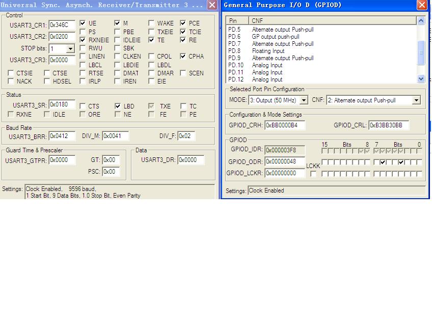
在网上搜了一下,有这方面的提问( 在2010-7-5 16:11:34 有提到过 一下为原帖 文字 USART3映射方式2(映射到PD8,PD9)时,要先开启AFIO功能,再初始化相关外设后,USART才有效。) m/ l% m8 B% k; l/ c9 S 以下代码是正确的: " }1 \$ Q& g' i7 x w u32 backRcc = RCC->APB2ENR & (RCC_APB2Periph_GPIOB | RCC_APB2Periph_AFIO);//read status of rcc_gpiob & rcc_afio$ Q2 T% X% O6 j) U1 E7 J RCC_APB2PeriphClockCmd(RCC_APB2Periph_GPIOB | RCC_APB2Periph_AFIO,ENABLE); GPIO_PinRemapConfig(GPIO_FullRemap_USART3,ENABLE); RCC_APB2PeriphClockCmd(RCC_APB2Periph_GPIOD,ENABLE); /* Configure USART3 Tx (PD.8) as alternate function push-pull */! m! I' S. }: t3 l GPIO_InitStructure.GPIO_Pin =GPIO_Pin_8; GPIO_InitStructure.GPIO_Speed = GPIO_Speed_50MHz;* F$ G% _6 A- o1 I) c GPIO_InitStructure.GPIO_Mode = GPIO_Mode_AF_PP;3 ]2 N5 X/ s" f7 C1 p GPIO_Init(GPIOD, &GPIO_InitStructure);- k/ P4 K' i" o( ` Z /* Configure USART3 Rx (PD.9) as input Up */ GPIO_InitStructure.GPIO_Pin = GPIO_Pin_9; GPIO_InitStructure.GPIO_Mode = GPIO_Mode_IPU;5 }) K, t0 W0 Q6 t1 ?* [, \ GPIO_Init(GPIOD, &GPIO_InitStructure); if(!backRcc)' V6 p) D w0 P: s9 u { RCC->APB2ENR &= ~backRcc; //restore }/ H6 T$ p4 j$ H* b5 c: h # @" |2 R7 L4 {/ q- b 初始化USART等。。。5 J4 {" M5 o9 _8 W 若去掉 RCC_APB2PeriphClockCmd(RCC_APB2Periph_GPIOB | RCC_APB2Periph_AFIO,ENABLE);1 f+ [1 E/ n$ i# [0 o& X + g1 z; u, |8 |# x6 ` 不正常! + n r3 X) T/ f2 ]: x* ? 8 f1 S2 _# |" J; X$ } ) 根据上述还是没有解决这个问题 (其他口的重映射验证都是OK的),所以又开了一下此贴,希望得到大家的帮助 ,本人代码如下 //重映射成功的 方式1 #ifdef DEFINE_UART_MAP_PORT_3 RCC_APB2PeriphClockCmd(RCC_APB2Periph_GPIOC|RCC_APB2Periph_AFIO , ENABLE); RCC_APB1PeriphClockCmd(RCC_APB1Periph_USART3, ENABLE); ; H' H, B5 N# l& h8 i. o/ A GPIO_PinRemapConfig(GPIO_PartialRemap_USART3 ,ENABLE); // GPIO_FullRemap_USART32 @8 r R- P/ h7 G% L1 m0 ~; V1 h /* Configure USART3 Tx (PC10) as alternate function push-pull */: h1 C8 I2 @% f/ `/ H" Z GPIO_InitStructure.GPIO_Pin = GPIO_Pin_10; GPIO_InitStructure.GPIO_Speed = GPIO_Speed_50MHz;. G. M1 ~+ ^! o* O6 r$ A GPIO_InitStructure.GPIO_Mode = GPIO_Mode_AF_PP; GPIO_Init(GPIOC, &GPIO_InitStructure); /* Configure USART3 Rx (PC11) as input floating */ GPIO_InitStructure.GPIO_Pin = GPIO_Pin_11; GPIO_InitStructure.GPIO_Mode = GPIO_Mode_IN_FLOATING; GPIO_Init(GPIOC, &GPIO_InitStructure); #endif . T) i2 |" N2 M' k9 j4 X/ S5 s ( F; O7 P8 s/ x0 x5 j8 w //方式2 重映射失败! ]% z: r9 N+ ]8 o5 D & ]) [/ v0 ?+ i6 c- l+ e #ifdef DEFINE_UART_MAP_3) y4 U' Q* G( r D6 Y7 { # Y- Q; U" R* z8 R9 E RCC_APB2PeriphClockCmd(RCC_APB2Periph_GPIOB | RCC_APB2Periph_AFIO,ENABLE); ) k L& r4 V! L3 _ RCC_APB1PeriphClockCmd(RCC_APB1Periph_USART3 , ENABLE); RCC_APB2PeriphClockCmd(RCC_APB2Periph_GPIOD|RCC_APB2Periph_AFIO , ENABLE);0 q! `: i- v; l0 b" _5 w% L GPIO_PinRemapConfig(GPIO_FullRemap_USART3 ,ENABLE); // GPIO_FullRemap_USART3 4 F9 s0 J; a. o' f$ E1 b2 M9 U9 p /* Configure USART3 Tx (PD9) as alternate function push-pull */3 j5 s6 A5 N7 d! N1 `, T* H* J GPIO_InitStructure.GPIO_Pin = GPIO_Pin_8; GPIO_InitStructure.GPIO_Speed = GPIO_Speed_50MHz; GPIO_InitStructure.GPIO_Mode = GPIO_Mode_AF_PP; GPIO_Init(GPIOD, &GPIO_InitStructure); /* Configure USART3 Rx (PD8) as input floating */0 {3 d* \2 j, R2 U GPIO_InitStructure.GPIO_Pin = GPIO_Pin_9; GPIO_InitStructure.GPIO_Mode = GPIO_Mode_IN_FLOATING;& V5 [& J* b8 ]" p: Y) `) E GPIO_Init(GPIOD, &GPIO_InitStructure);# A- x [* A3 u [$ A/ g #endif . O% j/ V3 H+ ^; J7 u8 U 附图为keil寄存器值 |

 微信公众号
微信公众号
 手机版
手机版

RE:stm32 USART3 映射方式2
RE:stm32 USART3 映射方式2
RE:stm32 USART3 映射方式2