|
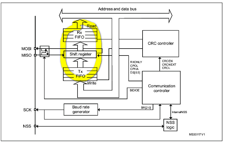
本帖最后由 woshilee 于 2014-12-16 19:55 编辑 M0的SPI终于调通了,玩儿M3,M4多了现在玩M0就有了固定的思维模式,老路走不通的话就要找它们之间的不同之处了贴上程序吧, i8 Z1 D% [- o #include "stm32f0xx.h" #include "stdio.h"% n# v/ e2 E/ g! k' ^* k uint8_t getbyte=0; /** * @brief Delay * @param None * @retval None) d- Y- D8 u' r8 ^9 i, k) t */ void delay1ms(unsigned int ms): r7 _, p. T, S3 x( G: t { unsigned int i,j;- h% S' U, I6 w& G2 Y6 S for(i=0; i<ms; i++) for(j=0; j<100; j++);- T: t# Y/ R& \1 f& V- V } l8 v _, \* p3 {4 n /**! y6 \1 q* o' u- |; N * @brief GPIO Config" b1 F* a: a% h2 Y * @param None * @retval None3 G$ ?4 [3 E# W! J" M4 ~) e/ x) C: X */ void GPIO_Configuration(void) { GPIO_InitTypeDef GPIO_InitStructure; /* Configure PA5£¬PA7 in output nopull mode */ GPIO_InitStructure.GPIO_Pin = GPIO_Pin_4|GPIO_Pin_5|GPIO_Pin_7; GPIO_InitStructure.GPIO_Mode = GPIO_Mode_AF; GPIO_InitStructure.GPIO_Speed = GPIO_Speed_50MHz;/ u3 @2 [, Y( `4 L v& N0 _ GPIO_InitStructure.GPIO_OType = GPIO_OType_PP;( A) J/ I; C- }. Z GPIO_InitStructure.GPIO_PuPd = GPIO_PuPd_UP;4 x# c- J, ^5 I1 f' R4 G" I GPIO_Init(GPIOA, &GPIO_InitStructure); * @# c: g$ x# ?9 v8 a0 w: ? : u/ R' n. |+ N4 H, M GPIO_InitStructure.GPIO_Pin = GPIO_Pin_6;- M- y' W5 b4 p // GPIO_InitStructure.GPIO_Mode = GPIO_Mode_IN; GPIO_InitStructure.GPIO_Mode = GPIO_Mode_AF;8 w9 N8 r- ]+ Y2 ` GPIO_InitStructure.GPIO_OType = GPIO_OType_PP;//ÍÆÍ츴ÓÃÊä³ö) s* {3 C0 L0 J3 f: G GPIO_InitStructure.GPIO_Speed = GPIO_Speed_50MHz; GPIO_InitStructure.GPIO_PuPd = GPIO_PuPd_UP;//Ðü¿Õ»òÉÏÀÊäÈë2 Z' x1 B: G2 ? GPIO_Init(GPIOA, &GPIO_InitStructure); 2 P L# f- W/ K GPIO_PinAFConfig(GPIOA,GPIO_PinSource4, GPIO_AF_0);) i V. q- g; j: ^& j0 e5 Q GPIO_PinAFConfig(GPIOA,GPIO_PinSource5, GPIO_AF_0); GPIO_PinAFConfig(GPIOA,GPIO_PinSource6, GPIO_AF_0); GPIO_PinAFConfig(GPIOA,GPIO_PinSource7, GPIO_AF_0); } void RCC_Configuration(void)3 D/ @- y7 i# H; ~6 n+ V3 o7 n0 ] {$ f* P, e% [3 u$ t+ e# `: g RCC_AHBPeriphClockCmd(RCC_AHBPeriph_GPIOA, ENABLE); RCC_APB2PeriphClockCmd(RCC_APB2Periph_SPI1, ENABLE);6 U3 i, X5 E7 p5 `2 t. v/ o& P }5 n9 p2 D/ J$ ? void SPI_Configuration(void) {% I- D0 O! O# C( u SPI_InitTypeDef SPI_InitStructure; SPI_InitStructure.SPI_Direction = SPI_Direction_2Lines_FullDuplex; ' J' m+ n1 w5 B- h% ]9 i SPI_InitStructure.SPI_DataSize = SPI_DataSize_8b; - S+ ^ L9 x" p( n! c6 N3 h# z SPI_InitStructure.SPI_CPOL = SPI_CPOL_Low;$ c+ n9 D! O3 ?3 u SPI_InitStructure.SPI_CPHA = SPI_CPHA_1Edge; P6 Y$ s( [/ k9 _0 M+ \ SPI_InitStructure.SPI_NSS = SPI_NSS_Soft; 1 F& s- }0 V! J: z/ n* C3 G SPI_InitStructure.SPI_BaudRatePrescaler = SPI_BaudRatePrescaler_256;2 n) T3 H2 I, I. w5 E" U SPI_InitStructure.SPI_FirstBit = SPI_FirstBit_MSB; 1 e7 r/ s0 C: F% E! T( }8 Y- | SPI_InitStructure.SPI_CRCPolynomial = 7; ' u; u* R+ V; i* i- h' z7 z SPI_InitStructure.SPI_Mode = SPI_Mode_Master;" o+ i. Q3 z1 f$ t" ^' t& m6 s5 m SPI_Init(SPI1, &SPI_InitStructure); + t$ D- m* e6 }8 o8 q( Y1 ? SPI_NSSInternalSoftwareConfig(SPI1, SPI_NSSInternalSoft_Set);* |0 L. z* H! n1 `; ~( Y, Z SPI_RxFIFOThresholdConfig(SPI1, SPI_RxFIFOThreshold_QF); ! l4 O! `/ I; y& v# h SPI_Cmd(SPI1, ENABLE); /* SPI enable */ 1 p7 T/ ]. e- }1 |- c5 O }% c( B2 N( \$ b* Y ; p; P. K, [8 \3 u7 V$ O 9 m% C4 U$ [$ p+ F6 g7 U2 H uint8_t SPI1_ReadWriteByte(uint8_t TxData) { uint8_t RxData = 0; while(SPI_I2S_GetFlagStatus(SPI1, SPI_I2S_FLAG_TXE) == RESET); //µÈ´ý·¢ËÍ»º³åÇø¿Õ & H) u# S5 y% @ I SPI_SendData8(SPI1, TxData); //·¢Ò»¸ö×Ö½Ú' _& D( Y4 r* g( G: ~. P" M$ K: f while(SPI_I2S_GetFlagStatus(SPI1, SPI_I2S_FLAG_RXNE) == RESET); RxData = SPI_ReceiveData8(SPI1);//SPI2 //·µ»Ø½ÓÊÕµ½µÄÊý¾Ý*/- q+ H4 G! M5 D* t return (uint8_t)RxData; & s) \ B* f( a2 E } 2 c) p. j7 ~2 n& a8 { ! \% l o6 Z0 m2 R/ n" ^ int main(void) o; W) Z- ~, e& n! s {' l- @" `7 h& F9 e r+ s( g3 m4 ^ RCC_Configuration(); GPIO_Configuration(); SPI_Configuration(); // NVIC_Configuration();. M' l* o/ s$ E$ [& l while (1) {- d4 ~; I' s/ ?0 I 2 n* |1 m9 e; S% d0 l& Z getbyte=SPI1_ReadWriteByte(0x55);9 L# D$ U2 y5 A; m9 d0 P! V delay1ms(100);0 Z `2 _# Z" v1 n/ O8 h }( ]" D9 ?0 d" V$ {- \ }, x) ?" f! B" q8 V 红色的语句在M3中是没有的,在M0中这个函数的定义如下:& H% q& H! \" a" r /**% X% H! e R5 t+ J! D6 r * @brief Configures the FIFO reception threshold for the selected SPI.: }- L% m! f B" H * @param SPIx: where x can be 1 or 2 to select the SPI peripheral.4 B9 D/ q( A+ } e% H: r' H6 b * @param SPI_RxFIFOThreshold: specifies the FIFO reception threshold.6 `2 r8 l A V: O: F; N4 U$ v. J * This parameter can be one of the following values: * @arg SPI_RxFIFOThreshold_HF: RXNE event is generated if the FIFO ' o7 L; C5 ^ m, F8 n5 G * level is greater or equal to 1/2. * @arg SPI_RxFIFOThreshold_QF: RXNE event is generated if the FIFO * level is greater or equal to 1/4. * n8 b5 }& ~* `0 [ * @retval None0 ~; M; K/ T2 G */ void SPI_RxFIFOThresholdConfig(SPI_TypeDef* SPIx, uint16_t SPI_RxFIFOThreshold)6 d4 R+ y5 Z5 q- \2 M0 B5 D% C { /* Check the parameters */ assert_param(IS_SPI_ALL_PERIPH(SPIx)); assert_param(IS_SPI_RX_FIFO_THRESHOLD(SPI_RxFIFOThreshold));( |& ]2 S5 D9 b) d1 r& ~: H5 S7 q /* Clear FRXTH bit */( p) Y) f9 d: t/ k+ F& F SPIx->CR2 &= (uint16_t)~((uint16_t)SPI_CR2_FRXTH); % f9 Y* @9 f0 H7 Q9 R4 }! B! w /* Set new FRXTH bit value */8 O3 ^; N+ Q* `2 Q SPIx->CR2 |= SPI_RxFIFOThreshold;3 e% @5 ]5 R8 L }. }% ~+ C$ v& _" p1 f 如果不加这句话的话,肯定会卡在判断RXNE位的地方,因为没有产生这个标志,如果用延时的代替的话是可以发送出去的,但是时序就会有问题,因为发送语句执行后不是立即就完成的。希望大家注意到这一点 1 C* N# v y8 P. z) F, [# a: X 所有SPI 数据换都通过32 位的嵌入式FIFO,设置FRXTH 位。 RXFIFO 的阈值必须和对SPIx_DR 寄存器的读访问的字长对齐比如发送的是8位的数据,就要设置SPI_RxFIFOThreshold_QF: RXNE event is generated if the FIFO *level is greater or equal to 1/4. 就是32/4=8--》1个字节& v5 X3 d; r8 `( m7 F5 d! r 如果发送的是16位数据就要设置SPI_RxFIFOThreshold_HF: RXNE event is generated if the FIFO *level is greater or equal to 1/2.就是 32/2=16--》2个字节0 i$ b; @ l" P |

 微信公众号
微信公众号
 手机版
手机版

我这是应该做的,跟你比就小巫见大巫啦