|
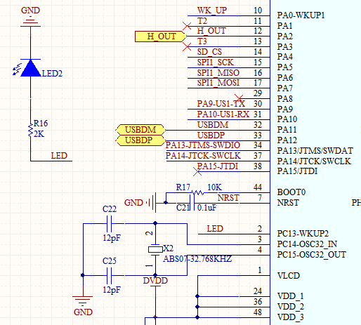
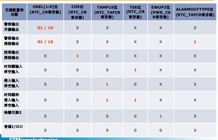
本帖最后由 wuwovicky 于 2015-3-11 13:12 编辑 原因:图一,画PCB时,因为看到PC13离LED比较近,就用PC13来驱动LED,查看手册后,也没说不能驱动LED,所以硬件是可以的。但是在调试软件时发现时钟点亮不了LED,然后在网上找资料,但都是STMF103系列的(PC13最大输出速度不能大于2MHZ,且不能驱动LED)。 STM32F103系列,当PC14,PC15外接晶振时,好像PC13不能当IO口使用,用过103的人谁帮忙验证下? 我又仔细看了下STM32L的参考手册(RM0038),7.3.15 Selection of RTC_AF1 alternate function章节,可以当IO口使用,于是启动KEIL调试,查看图二所描述的寄存器, RTC->CR OSE位L[1:0] = 00;RTC->CR COE位= 0; RTC_TAFCR TAMP1E位 = 0; RTC->CR TSE位 = 1; PWR_CS EWUP2 = 0; 对照图二发现RTC->CR TSE位被置一了,对应的功能是时间戳侵入和侵入输入,浮空输入,所以只要将改为置0,就能够使用普通IO口功能了。 void LED_Config(void) { GPIO_InitTypeDef GPIO_InitStructure; RCC_AHBPeriphClockCmd(RCC_AHBPeriph_GPIOC,ENABLE); /* Configure the test LED pin */ GPIO_InitStructure.GPIO_Pin = GPIO_Pin_13; GPIO_InitStructure.GPIO_Mode = GPIO_Mode_OUT; GPIO_InitStructure.GPIO_OType = GPIO_OType_PP; GPIO_InitStructure.GPIO_PuPd = GPIO_PuPd_UP; GPIO_InitStructure.GPIO_Speed = GPIO_Speed_40MHz; GPIO_Init(GPIOC, &GPIO_InitStructure); } void RTC_Config(void) { /* Enable the PWR clock */ RCC_APB1PeriphClockCmd(RCC_APB1Periph_PWR, ENABLE); /* Allow access to RTC */ PWR_RTCAccessCmd(ENABLE); #if defined (RTC_CLOCK_SOURCE_LSI) /* LSI used as RTC source clock*/ /* The RTC Clock may varies due to LSI frequency dispersion. */ /* Enable the LSI OSC */ RCC_LSICmd(ENABLE); /* Wait till LSI is ready */ while(RCC_GetFlagStatus(RCC_FLAG_LSIRDY) == RESET) { } /* Select the RTC Clock Source */ RCC_RTCCLKConfig(RCC_RTCCLKSource_LSI); SynchPrediv = 0xFF; AsynchPrediv = 0x7F; #elif defined (RTC_CLOCK_SOURCE_LSE) /* LSE used as RTC source clock */ /* Enable the LSE OSC */ RCC_LSEConfig(RCC_LSE_ON); /* Wait till LSE is ready */ while(RCC_GetFlagStatus(RCC_FLAG_LSERDY) == RESET) { } /* Select the RTC Clock Source */ RCC_RTCCLKConfig(RCC_RTCCLKSource_LSE); SynchPrediv = 0xFF; AsynchPrediv = 0x7F; #else #error Please select the RTC Clock source inside the main.c file #endif /* RTC_CLOCK_SOURCE_LSI */ /* Enable the RTC Clock */ RCC_RTCCLKCmd(ENABLE); /* Wait for RTC APB registers synchronisation */ RTC_WaitForSynchro(); /* Enable The TimeStamp */ RTC_TimeStampCmd(RTC_TimeStampEdge_Rising, DISABLE); //RTC->CR TSE位清0 RTC_TimeStampCmd(RTC_TimeStampEdge_Falling, DISABLE); //RTC->CR TSE位清0 } 成功点亮LED,并且能够使用RTC |
å¾ä¸

å¾äº

å¾ä¸

 微信公众号
微信公众号
 手机版
手机版

对的,2.4*4.1厘米
哈哈,还行~