本帖最后由 电子星辰 于 2018-6-17 21:19 编辑
开发环境:WIN7_64位系统;Keil MDK5;STM32CubeMX。(Java环境(Cube必须))
1、下载并安装好STM32CubeF0_V1.9.0,USB驱动:STSW_LINK009_V2.0.0。
2、随便找一根MicroUSB的安卓手机线连接Nucleo板和电脑就可以了。
上电之后LED1先亮,随后LED2亮起,LED3闪烁。将D2和GND的跳线帽拔掉,LED3闪烁频率加快。

找到官方的例程代码
...\Repository\STM32Cube_FW_F0_V1.9.0\Projects\STM32F042K6-Nucleo\Examples\GPIO\GPIO_IOToggle
这个例程是展示,通过HAL API来配置GPIO的。我觉得例程说明比较像板载的原始代码。
编译,下载。
下载失败。。。

打开设置里-Debug-STLink Debugger的Settings-Flash Download
点Add,选32K的。
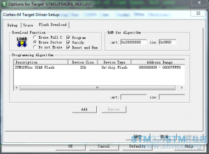
好,这次可以了。
这时,LED3闪烁频率加快,拔掉跳线帽也对闪烁没有影响。哦豁,下错了。
附一下例程部分代码:
- int main(void)
- {
- /* This sample code shows how to use GPIO HAL API to toggle LED3 IO
- in an infinite loop. */
- /* STM32F0xx HAL library initialization:
- - Configure the Flash prefetch
- - Systick timer is configured by default as source of time base, but user
- can eventually implement his proper time base source (a general purpose
- timer for example or other time source), keeping in mind that Time base
- duration should be kept 1ms since PPP_TIMEOUT_VALUEs are defined and
- handled in milliseconds basis.
- - Low Level Initialization
- */
- HAL_Init();
- /* Configure the system clock to 48 MHz */
- SystemClock_Config();
-
- /* -1- Enable GPIO Clock (to be able to program the configuration registers) */
- LED3_GPIO_CLK_ENABLE();
- /* -2- Configure IO in output push-pull mode to drive external LEDs */
- GPIO_InitStruct.Mode = GPIO_MODE_OUTPUT_PP;
- GPIO_InitStruct.Pull = GPIO_PULLUP;
- GPIO_InitStruct.Speed = GPIO_SPEED_FREQ_HIGH;
- GPIO_InitStruct.Pin = LED3_PIN;
- HAL_GPIO_Init(LED3_GPIO_PORT, &GPIO_InitStruct);
- /* -3- Toggle IO in an infinite loop */
- while (1)
- {
- HAL_GPIO_TogglePin(LED3_GPIO_PORT, LED3_PIN);
- /* Insert delay 100 ms */
- HAL_Delay(100);
- }
- }
|
 微信公众号
微信公众号
 手机版
手机版


