|
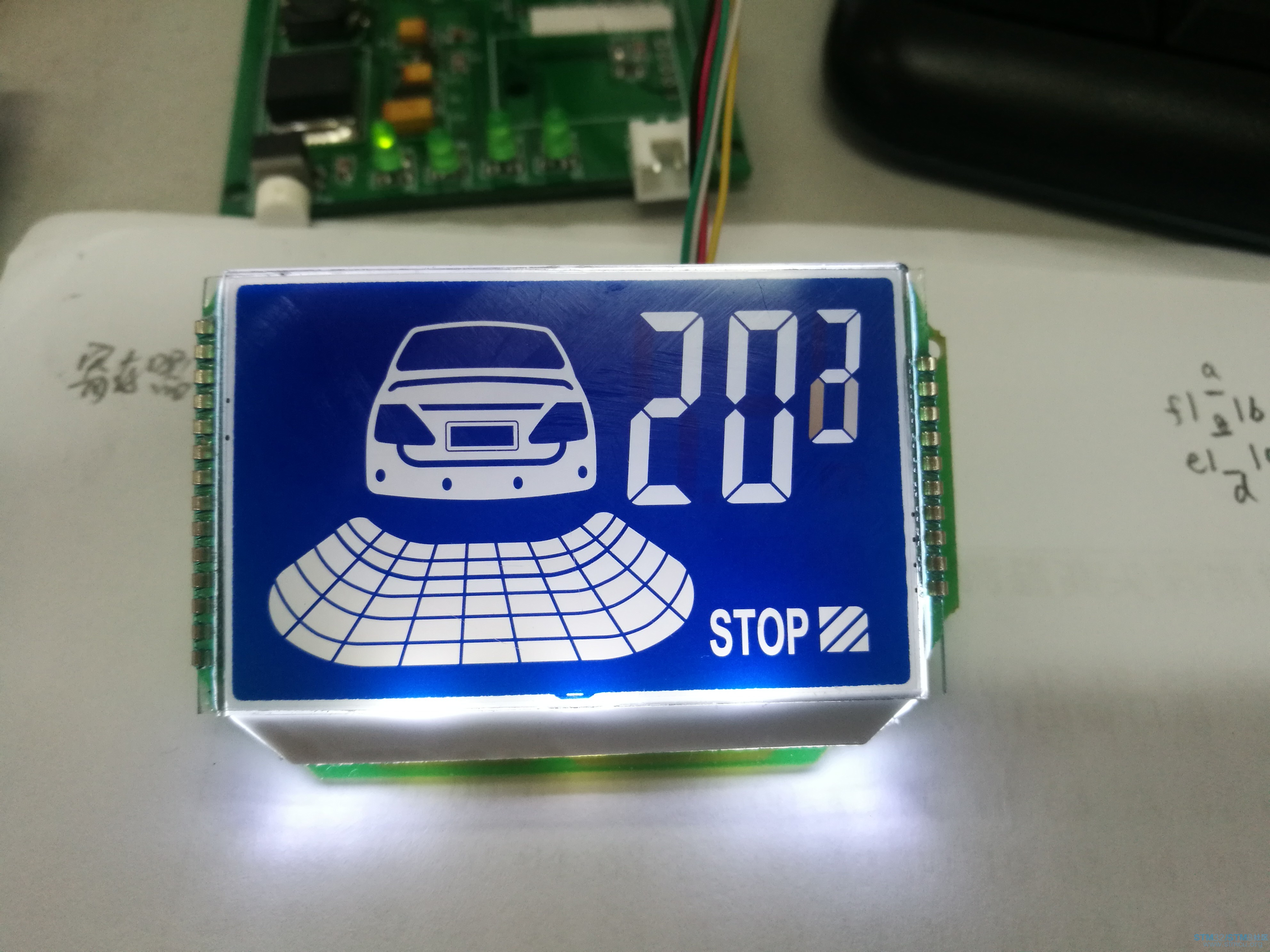
拆了一个雷达小显示盒,里面使用的TM1723芯片驱动段码屏,拿来练练手,使用STM32F103RTB6驱动。 //TM1723.C #include "config.h" const u8 dispdat[]={0xd7,0x06,0xe3,0xa7,0x36,0xb5,0xf5,0x07,0xf7,0xb7}; //TM1723初始化 void Init_TM1723(void) { GPIO_InitTypeDef GPIO_InitStructure; RCC_APB2PeriphClockCmd(RCC_APB2Periph_GPIOA, ENABLE); GPIO_InitStructure.GPIO_Pin = GPIO_Pin_1|GPIO_Pin_2|GPIO_Pin_3; GPIO_InitStructure.GPIO_Mode = GPIO_Mode_Out_PP; GPIO_InitStructure.GPIO_Speed = GPIO_Speed_50MHz; GPIO_Init(GPIOA, &GPIO_InitStructure); GPIO_SetBits(GPIOA,GPIO_Pin_1|GPIO_Pin_2|GPIO_Pin_3); } //延时 void TM1723_Delayus(u32 ys) { u8 i; u32 j; for(j=0;j<ys;j++) { for(i=0;i<5;i++); //´óÔ¼1us } } //TM1723写字节 void TM1723_WriteByte(u8 dat) { u8 i; for(i=0;i<8;i++) { TM1723_CLK=0; if( (dat&0x01)==0x01 ) { TM1723_DIO=1; } else { TM1723_DIO=0; } dat=dat>>1; TM1723_CLK=1; TM1723_Delayus(2); //2us } } //tm1723写命令 void TM1723_WriteCmd(u8 cmd) { TM1723_CLK=1; TM1723_STB=0; TM1723_WriteByte(cmd); TM1723_STB=1; TM1723_Delayus(100); //100us } //tm1723写数据 void TM1723_WriteDat(u8 addr, u8 dat) { TM1723_CLK=1; TM1723_STB=0; TM1723_WriteByte(addr); TM1723_Delayus(50); TM1723_WriteByte(dat); TM1723_STB=1; TM1723_Delayus(100); //100us } //测试 void tt(u8 i) { TM1723_WriteCmd(0x00); TM1723_WriteCmd(0x44); TM1723_WriteDat(0xc0, 0x00); TM1723_WriteDat(0xc1, 0x00); TM1723_WriteDat(0xc2, dispdat[(i%100)%10]); TM1723_WriteDat(0xc3, dispdat[(i%100)/10]); TM1723_WriteDat(0xc4, dispdat[i/100]); TM1723_WriteDat(0xc5, 0xff); TM1723_WriteDat(0xc6, 0x00); TM1723_WriteDat(0xc7, 0x00); TM1723_WriteDat(0xc8, 0x00); TM1723_WriteDat(0xc9, 0xff); TM1723_WriteDat(0xca, 0xff); TM1723_WriteDat(0xcb, 0xff); TM1723_WriteDat(0xcc, 0xff); TM1723_WriteDat(0xcd, 0x00); TM1723_WriteDat(0xce, 0xff); TM1723_WriteDat(0xcf, 0xff); TM1723_WriteCmd(0x97); } //TM1723.H #ifndef __TM1723_H_ #define __TM1723_H_ #define TM1723_DIO PAout(1) // PA1 #define TM1723_CLK PAout(2) // PA2 #define TM1723_STB PAout(3) // PA3 extern void Init_TM1723(void); extern void tt(u8 i); #endif 最后显示的图片 
|
 微信公众号
微信公众号
 手机版
手机版

测试的时候,最后一位间隔时间有点短
感谢大佬分享