
|
本帖最后由 点点&木木 于 2019-4-12 23:57 编辑 7 W% T+ {! ?0 u: A( ? 硬件组件 STM32 Nucleo-F746ZG × 1 博世BMI088 × 13 跳线(通用) × 1 # _8 u! C* F1 W8 W" t$ E6 U$ [手动工具和制造机器 烙铁(通用) 焊料空气流动站 信号分析仪 # e( h% g$ l5 }' C/ k, j 介绍 在这个项目中,我描述了我在Ada中的小型奥德赛,用于嵌入式ARM从头开始创建冗余IMU(使用多个6DoF陀螺仪/加速传感器)和软件环境来控制它。 我还将向您展示我用来达到目标的工具和方法(调试,分析器......)来估算一组6DoF IMU的音高和滚动: ' c, I2 F2 j' c6 ?- _2 Cfile:///C:/Users/ADMINI~1/AppData/Local/Temp/msohtmlclip1/01/clip_image001.png

* E, b* F2 A* n" B8 {2 g 局限性: 在本教程中,我没有描述控制火箭副翼或如何减少偏航旋转的PID过程,而只描述如何获取数据并估算滚转和俯仰。工作正在进行中,将在单独的教程中进行描述。 $ ^, @$ N+ o/ Z! ]/ _$ z动机: 对于正在进行的业余火箭项目,我们需要一个能够容忍各种加速度(和陀螺仪)的IMU,而无需在飞行范围内重新配置。此外,我们希望有一个多IMU板用于可靠性和过滤目的。 出于这个原因,我设计了一个冗余的BMI088(13x IMU),试图在高振动环境中获得最佳结果,一个业余火箭和高精度无人机。 在我们的使用案例中,它将被放置在如下的火箭中,连接到托管微控制器的板,该微控制器能够控制和处理来自传感器的数据。 ' ], d, ?2 t& N) p8 i, y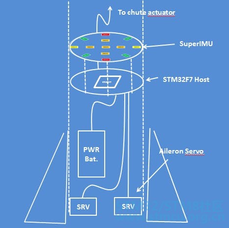
使用AdaCore框架和工具链将使我们能够从他们提供的强大编码环境中受益(在安全/可靠性导向的行业中得到高度认可,如航空航天和运输)。 我注意到在代码实现过程中,Ada代码,特别是在AdaCore GitHubrepo中编辑的代码很容易阅读。对于像我这样习惯于C /C ++和java环境的人来说,使用Ada并不是特别难。 " F/ |" w' a! U, x1 j, u& V语境: SuperIMU已被开发用于CNRS PlaneteScience的业余火箭队。它将有助于在高速和变化的振动环境中计算精确俯仰/滚转,以在飞行期间使用副翼稳定火箭。 7 A: {- y5 p, H E$ B/ { 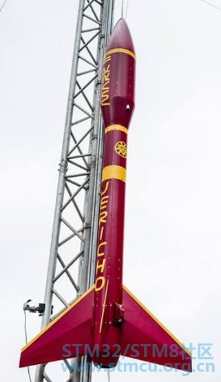
火箭的第一个目标 5 S+ h; E' ~$ |6 M7 HSuperIMU必须嵌入芯径小于90mm中。 - ]7 ^ f. u( R/ X/ G; k, J, d1 U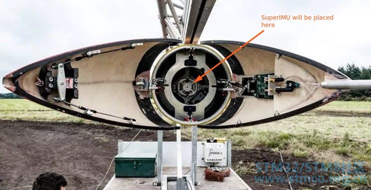
Z% a6 i1 x# l4 M& I8 e% ?$ t! _ 第1步:系统描述 SuperIMU具有13倍冗余6DoF IMU,可以直径50mm。它将使用SPI接口与微控制器通信,以获取原始数据(加速度和陀螺仪数据)。 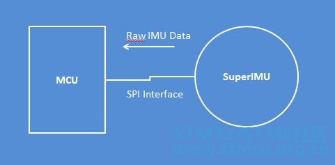
板载配置 我们使用简单的架构来可视化和测试SuperIMU。 微控制器使用SPI端口从SuperIMU过滤原始数据(加速度,角度速率),并估算角度。出于测试目的,它使用UART端口发送角度值。 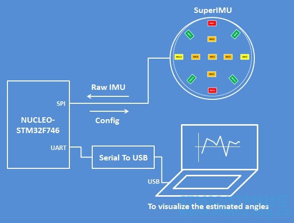
测试configuartion UART端口连接到计算机,以串行到USB模块可视化数据。 该项目的下一步是为SuperIMU创建一个特定的主机板。主机板将是圆形的,并嵌入STM32F746微控制器。 IMU按以下方式分布,呈星形: . `( p1 x" w X n 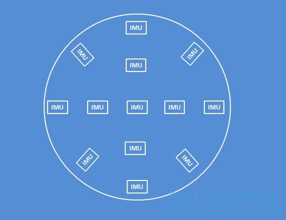
角度分布遵循45°模式: 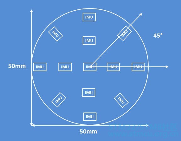
选择了先前的模式以最大化表面上IMU的存在。根据在德克萨斯大学(RedundantIMU Configurations:paper)进行的几何研究,其中测试了不同的几何配置: 传感器的3D空间中的几何分布比计划中的分布更好的结果(我们的情况) 分布对加速度没有影响(aDOP Accelaration Dilution of Precision) 分布对旋转精度有影响(wDOP角精度稀释) 我们添加的IMU越多,我们的精确度就越高 IMU的方向对结果没有显着影响 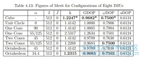
我们记住这个研究,为了达到像配置这样的立方体,我们可以将两个SuperIMU并行叠加。目前我们继续使用UnitCircle配置,尝试从中获取最大值。 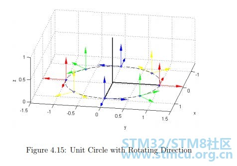
灵敏度范围配置:火箭模式 在业余火箭中,在飞行的最初几秒内,加速度可以达到8到9克。我们在滑槽开口和落地时观察到了一阵骚动。 这是一个典型的飞行日志(加速度/速度)的业余火箭与三个阶段(推进,上升无推进,滑槽开放,潜水与滑槽,地面接触): 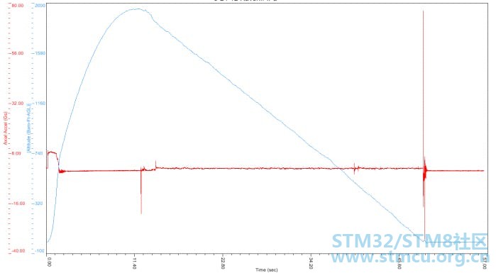
在短途飞行期间,典型的加速曲线如下: 发射<7秒:加速度> 6g 在降落伞开启前<11s,无推进上升:<3g 用降落伞潜水<50s:<3 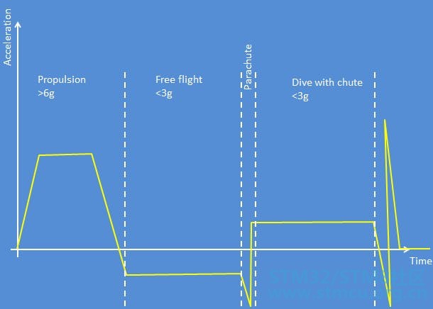
在飞行期间,感应范围需要容忍低和高,以无缝地进行精确控制。IMU的范围将在发布前配置。目前我将尝试四种不同的配置,当然这些配置不是确定的,它们需要通过实验进行调整: 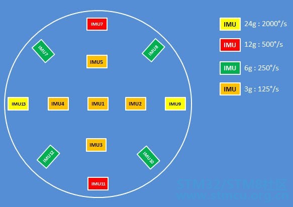
IMU分布,范围和名称 在飞行期间,将根据配置的范围忽略传感器原始值: 
过滤过程 在开始使用它们的俯仰/滚转估计之前,根据它们的范围过滤来自IMU的采集数据(加速度,角速度)。 范围过滤器: 过滤器获取原始数据,并根据每个IMU的配置范围,仅输出低于阈值的值:配置范围的95%。 范围滤波器还根据配置的范围提供每个测量数据的权重。权重用于取消高范围值的影响,它由平均过滤器使用。 权重具有以下值:0,1 / 2,1 / 4,1 / 8。 例如,如果IMU的范围是3G并且测量的加速度是2.9G,则范围滤波器输出来自该IMU的值为0的权重。 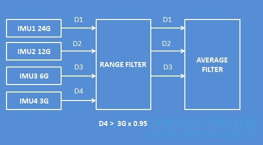
例如,如果测量的加速度<1G,则最准确的IMU是配置有3G范围的IMU。3G IMU的重量为1,6G IMU的重量为1/2,12G IMU的重量为1/4,24G IMU的重量为1/8。 权重根据下表计算: 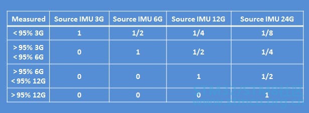
例外,当测量数据> 24%> 95%时,它不会为零加权。它会避免产生价值。 范围滤波器的输出值是每个IMU的四倍(加速度,加速度,陀螺仪,陀螺仪等)。 & t; L5 k; M3 ?) K5 u d6 ~7 a 平均过滤器: 该过滤器根据每个重量计算平均值。当权重为空时,不考虑测量值。 平均滤波器输出滤波数据,该数据是3轴的耦合(accel_filtered-xyz,gyro_filtered-xyz)。 滚动/间距估算器: 然后使用经过滤的数据来估计滚转角和俯仰角。使用众所周知的互补滤波器来估计飞行角度。 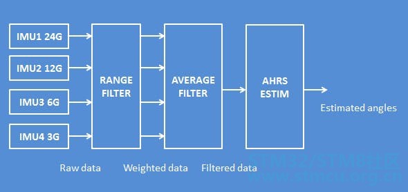
TimeSampling 目标st具有估计角度@ 1ms的采样率。这意味着我们需要测量所有13xIMU,在1ms的时间范围内进行滤波和补充估计。 第2步:使用硬件 IMU传感器BMI088 使用的传感器是BMI088,它专为无人机和机器人设计: 它可以承受24g的加速度。 SPI运行速度最高为10Mhz。 分辨率:0.09mg,0.004°/ s 低TCO为0.2 mg / K,低光谱噪声仅为230 pg / sqrt(Hz)最大值 输出数据速率:1.6kHz - 每个加速度为0.6ms - 陀螺仪最大为2000Hz - 每个0.5ms Nucleo-F746ZG的描述: 核板最有趣的是它们嵌入了ST Link V2-1编程接口以允许调试(例如使用OpenOCD或St-Util)。 它运行@ 216Mhz,非常适合需要快速采集和计算以获得最佳采样时间的用例。 您只需使用micro usb电缆将电路板连接到计算机。对于我的情况,我使用Ubuntu 18.x,自动检测到电路板,无需安装任何驱动程序。 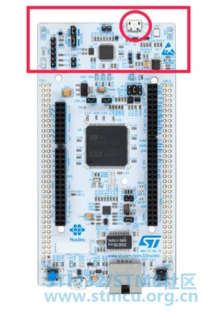
Nucleo主板的另一个有趣之处在于它们与ArduinoUno标头保持兼容。在下面以绿色(D0 ... D13)呈现。 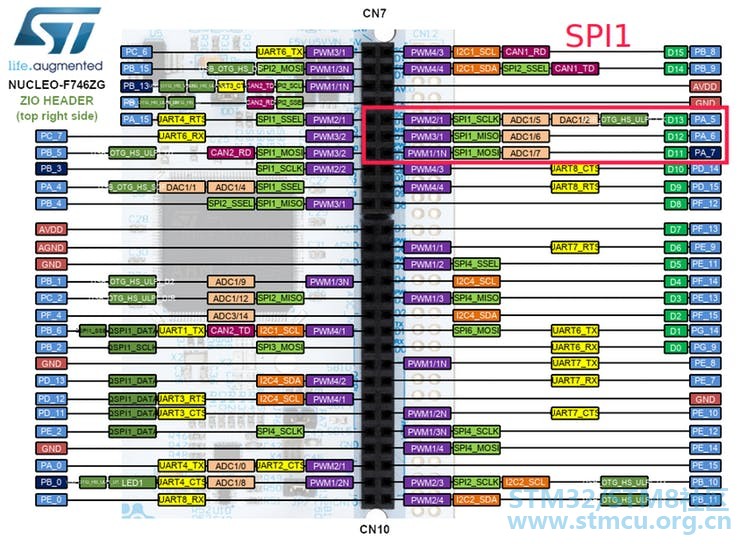
资料来源:https://os.mbed.com/platforms/ST-Nucleo-F746ZG/ 8 k: [" D' V- _6 ]/ c 由于我们需要在读取BMI088传感器(13x IMU)时将延迟降至最大,因此我们使用SPI端口获取Accel和Gyro数据(在这种情况下,I2C不适用)。 对于代码,我们将使用STM32F746的SPI1: SCK:PA_5 MISO:PA_6 MOSI:PA_7 Super IMU的描述: SuperIMU基于BMI088,它使用SPI接口配置和获取IMU的数据。从数据表中,用户电路如下: 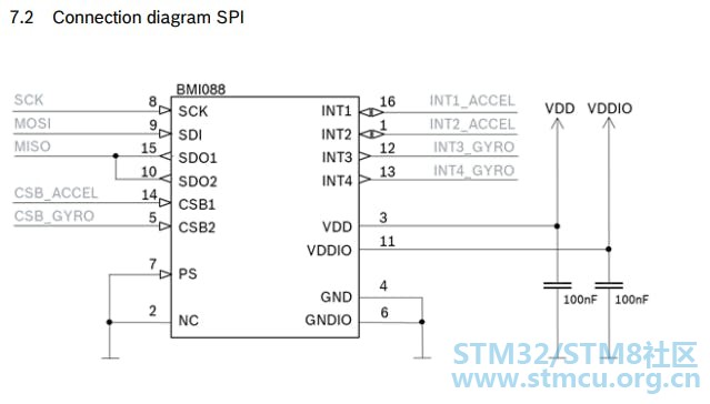
在SuperIMU的情况下,没有使用中断,它按顺序获取数据。ACCEL和GYRO的SDO在电路板中输出相同的输出。 我必须单独选择每个Gyro和Accel。 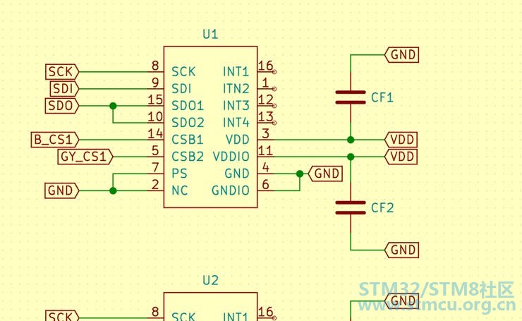
AdaIMU BMI088 Circle(SuperIMU)的原理图 SuperIMU的设计可以使用单个SPI获取数据(下一个版本将使用多个SPI),它具有13x BMI088: 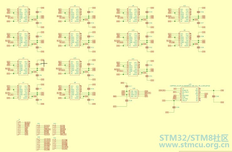
这是它的样子。我需要焊接接头以连接杜邦线: 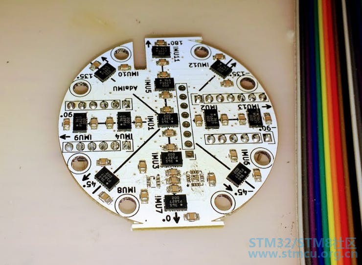
在后面有引脚的描述,SPI(SDO / SCK / SDI)以及用于选择陀螺仪和引脚的引脚: 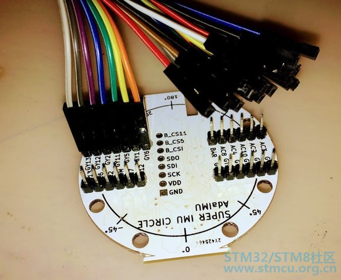
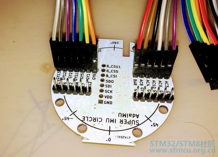
$ Z$ e5 w2 M5 |7 p c 1 \ c- [/ N4 [) i8 f7 ]4 I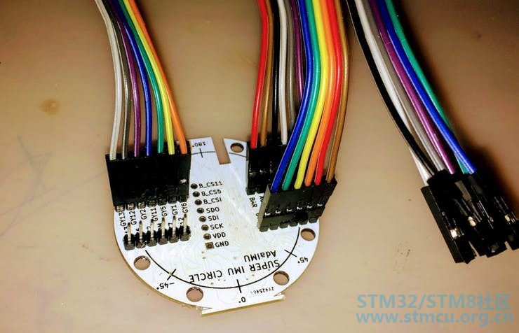
完成焊接后的样子如下: 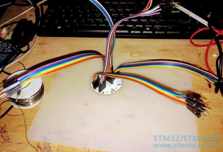
La pieuvre: 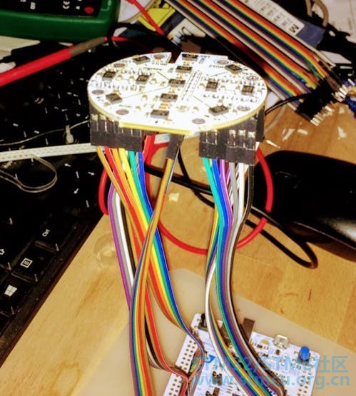
8 K/ Q' H/ i- J) Z8 E9 | 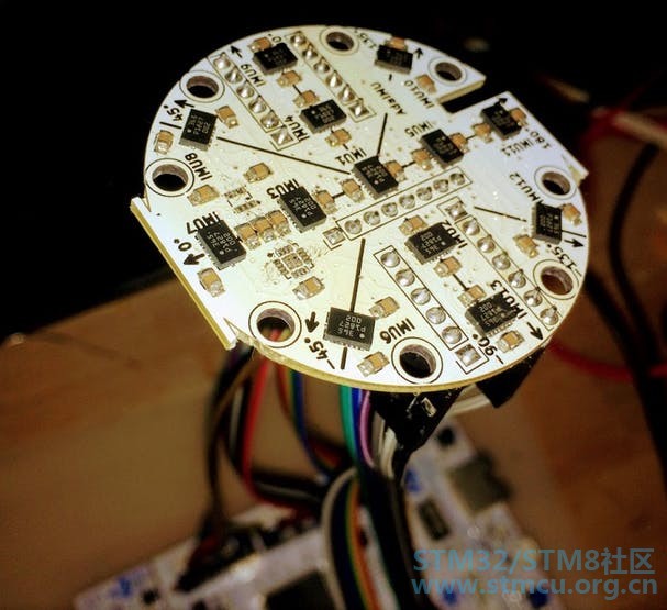
SuperIMU使用3v3电源和SPI端口1连接到Nucleo板。 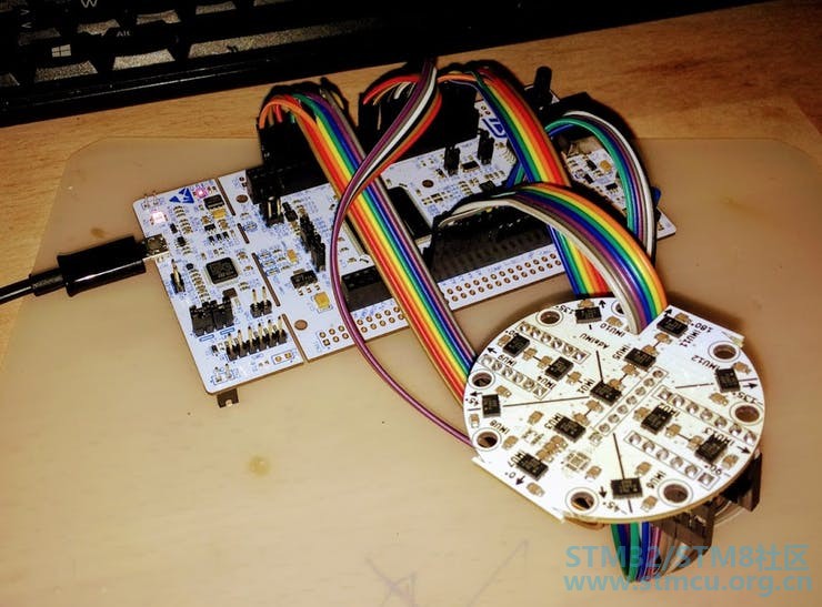
GPIO引脚用于选择Gyro,13x IMU的Accel将按如下方式完成: 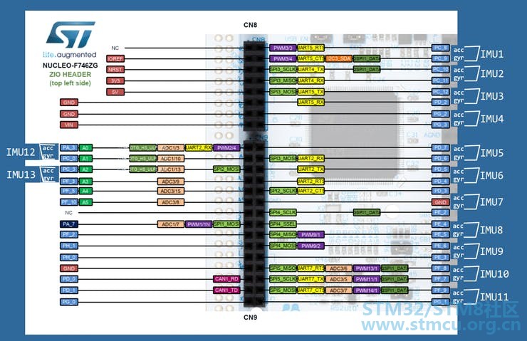
用于选择IMU的陀螺仪/加速度计的GPIO引脚的定义: -- IMU select IMU1_SPI1_SELC : GPIO_Point renames PC8; IMU1_SPI1_SELG : GPIO_Point renames PC9; IMU2_SPI1_SELC : GPIO_Point renames PC10; IMU2_SPI1_SELG : GPIO_Point renames PC11; IMU3_SPI1_SELC : GPIO_Point renames PC12; IMU3_SPI1_SELG : GPIO_Point renames PD2; IMU4_SPI1_SELC : GPIO_Point renames PG2; IMU4_SPI1_SELG : GPIO_Point renames PG3; IMU5_SPI1_SELC : GPIO_Point renames PD7; IMU5_SPI1_SELG : GPIO_Point renames PD6; IMU6_SPI1_SELC : GPIO_Point renames PD5; IMU6_SPI1_SELG : GPIO_Point renames PD4; IMU7_SPI1_SELC : GPIO_Point renames PD3; IMU7_SPI1_SELG : GPIO_Point renames PE2; IMU8_SPI1_SELC : GPIO_Point renames PE4; IMU8_SPI1_SELG : GPIO_Point renames PE5; IMU9_SPI1_SELC : GPIO_Point renames PE6; IMU9_SPI1_SELG : GPIO_Point renames PE3; IMU10_SPI1_SELC : GPIO_Point renames PF8; IMU10_SPI1_SELG : GPIO_Point renames PF7; IMU11_SPI1_SELC : GPIO_Point renames PF9; IMU11_SPI1_SELG : GPIO_Point renames PG1; IMU12_SPI1_SELC : GPIO_Point renames PA3; IMU12_SPI1_SELG : GPIO_Point renames PC0; IMU13_SPI1_SELC : GPIO_Point renames PC3; IMU13_SPI1_SELG : GPIO_Point renames PF3; IMU_SPI1_SEL_Points : constant STM32.GPIO.GPIO_Points := (IMU1_SPI1_SELC, IMU1_SPI1_SELG, IMU2_SPI1_SELC, IMU2_SPI1_SELG, IMU3_SPI1_SELC, IMU3_SPI1_SELG, IMU4_SPI1_SELC, IMU4_SPI1_SELG, IMU5_SPI1_SELC, IMU5_SPI1_SELG, IMU6_SPI1_SELC, IMU6_SPI1_SELG, IMU7_SPI1_SELC, IMU7_SPI1_SELG, IMU8_SPI1_SELC, IMU8_SPI1_SELG, IMU9_SPI1_SELC, IMU9_SPI1_SELG, IMU10_SPI1_SELC, IMU10_SPI1_SELG, IMU11_SPI1_SELC, IMU11_SPI1_SELG, IMU12_SPI1_SELC, IMU12_SPI1_SELG, IMU13_SPI1_SELC, IMU13_SPI1_SELG); IMU_SPI1_Accel_SEL_Points : array (1 .. 13) of access GPIO_Point'Class := ( IMU1_SPI1_SELC'Access, IMU2_SPI1_SELC'Access, IMU3_SPI1_SELC'Access, IMU4_SPI1_SELC'Access, IMU5_SPI1_SELC'Access, IMU6_SPI1_SELC'Access, IMU7_SPI1_SELC'Access, IMU8_SPI1_SELC'Access, IMU9_SPI1_SELC'Access, IMU10_SPI1_SELC'Access, IMU11_SPI1_SELC'Access, IMU12_SPI1_SELC'Access, IMU13_SPI1_SELC'Access ); IMU_SPI1_Gyro_SEL_Points : array (1 .. 13) of access GPIO_Point'Class := ( IMU1_SPI1_SELG'Access, IMU2_SPI1_SELG'Access, IMU3_SPI1_SELG'Access, IMU4_SPI1_SELG'Access, IMU5_SPI1_SELG'Access, IMU6_SPI1_SELG'Access, IMU7_SPI1_SELG'Access, IMU8_SPI1_SELG'Access, IMU9_SPI1_SELG'Access, IMU10_SPI1_SELG'Access, IMU11_SPI1_SELG'Access, IMU12_SPI1_SELG'Access, IMU13_SPI1_SELG'Access ); 4 n. N" D6 t+ I3 \7 k# _0 B ; q, J( k; ~4 v% B6 W$ H 第3步:软件设置/ IDE 使用Adacore GPS IDE 我从Adacore网站安装了GPS IDE:gnat-community-2018-20180528-x86_64-linux-bin,它有一个很酷的编辑器,包括debuging界面和Ada和SPARK的所有检查环境。 我从Adacore网站安装了Arm-ELF编译器:gnat-community-2018-20180524-arm-elf-linux64-bin,它为ARM(以及bb-runtimes)提供编译器和构建器工具链。 使用项目的代码 要使用该软件,您需要克隆此分支http://github.com/LaetitiaEl/Ada_Drivers_Library,此存储库基于Ada驱动程序库:AdaCore /Ada_Drivers_Library 使用./GNAT/2018/bin/gps 打开项目文件:Ada_Drivers_Library / examples /STM32F746_Nucleo / SuperIMU.gpr 你编译/上传,这就是全部! 该项目针对STM32F746,如果需要可以轻松移植到STM32F4(通过github或黑客联系我寻求帮助)。 第4步:首先进行眨眼测试! 在继续之前,我需要确保可以正确编程电路板。 ( j/ S4 N. H: G! N: @( Q9 S: P' K A 我保留了现有文件:blinky_f7disco.gpr,并修改了以下路径。继续使用stm32f746_discovery_full.gpr没问题 blinky_f7disco使用以下主条目: Ada_Drivers_Library/examples/shared/hello_world_blinky/src/blinky.adb7 c; _1 }8 x* y, Y ~/ d blinky的内容如下: with STM32.Board; use STM32.Board;with STM32.GPIO; use STM32.GPIO;- F8 ]! a$ H6 s: A$ Z0 k with Ada.Real_Time; use Ada.Real_Time;# x4 V$ d! x' ]& W procedure Blinky is Period : constant Time_Span := Milliseconds (200); -- arbitrary Next_Release : Time := Clock; begin STM32.Board.Initialize_LEDs; loop Toggle (All_LEDs);2 M! ^) H* ^: K& _ Next_Release := Next_Release + Period;' w6 Q0 n {& N6 T delay until Next_Release;! A/ _9 ~7 H; Y. _ end loop;: ]/ L; R+ x, P6 P" L( P) q end Blinky; # }% M8 ?9 l' Y1 v! {! { 似乎这个代码对所有主板都是通用的。使用GPS IDE我遵循All_LED的定义,它定义于: Ada_Drivers_Library/boards/stm32_common/stm32f746disco/stm32-board.ads1 d2 S$ ~. J% }& i 值All_LEDs是索引为1的集合,指向PI1: Green_LED : User_LED renames PI1;6 n/ H# r4 e- `5 Z8 g" ` i# r" rLED1 : User_LED renames Green_LED;% t+ s5 O. y& | H* r" [. A8 A) j LCH_LED : User_LED renames Green_LED;; @- Y* J+ g4 [ All_LEDs : GPIO_Points := (1 => Green_LED); - K6 v Q/ ^9 y. o; f5 r. c 在Nucleo板上没有LED连接到PI1,找出我可以使用的输出,简单的方法是检查核板的原理图http://www.st.com/resource/en/sc ... leo_144pins_sch.zip 8 G* Q/ k. v P2 y$ B 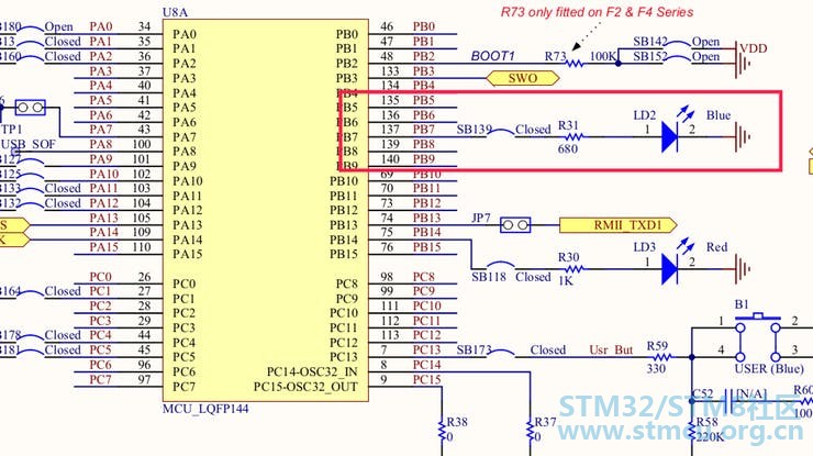
我把蓝色LED连接到PB7。然后代码更新为蓝色:Blue_LED : User_LED renames PB7; LED1 : User_LED renames Blue_LED; LCH_LED : User_LED renames Blue_LED;+ u9 a: m% C2 R& A7 s All_LEDs : GPIO_Points := (1 => Blue_LED);9 s$ V6 W3 Q% M1 }. A2 M 8 F8 A, F' v* Y 然后使用上传按钮上传代码(重要的是您需要配置上传/调试,在我的情况下,我使用OpenOCD,如下所述) 
代码编译得很好,正确上传并且蓝色LED闪烁: 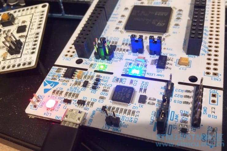
让我们开始认真的工作。为BMI088制作SPI驱动程序。 0 P& b- J7 T, `9 Y$ \# w- P% M第5步:为BMI088制作驱动程序 很酷的是,Ada_Drivers_Library已经在“components / src / motion”目录中提供了一些SPI IMU示例。 我只需要使用l3gd20来启动bmi088的驱动程序以获得灵感。 
要正确选择寄存器和协议特性,请使用以下资源: - BST-BMI088-DS001- officiel C驱动程序:有助于获得时间 有关信息,现有驱动程序的演示位于路径中:Ada_Drivers_Library/ arch / ARM / STM32 / driver_demos / 更新板定义:定义SPI1在STM32.Board包体中的文件stm32-board.ads中,我们添加: -- SPI1 / IMU BMI088 example -- ---------------------------------% |. s" A9 F8 Q# S" m -- SPI Port4 n/ x/ T% E2 V/ c$ i7 C- h: C IMU_SPI : SPI_Port renames SPI_1;2 F4 q! ^- p6 x% o0 F2 P -- SPI IOs! c" E# O/ F1 y3 n* m' x9 o SPI1_SCK : GPIO_Point renames PA5; -- D13 in connector CN10 SPI1_MISO : GPIO_Point renames PA6; -- D14 in connector CN10- O2 G2 v3 G% f" E# e" I, Q$ U SPI1_MOSI : GPIO_Point renames PA7; -- D15 in connector CN10: v. c2 D* G+ G -- IMU select IMU_SEL1 : GPIO_Point renames PG9; -- D0 in connector CN103 v3 n( E& G% @; a+ A# t -- To initialize the SPI1 port for the BMI088+ B2 s( [( M. }( a; `) k, m procedure Initialize_SPI1_For_BMI088;- i5 `' c5 O; i* g 在STM32F7中使用8位SPI的技巧 BIM088与8位通信非常重要。但是数据tx / rx DR寄存器是16位,默认情况下它发送16位。首先写入/读取:NOK 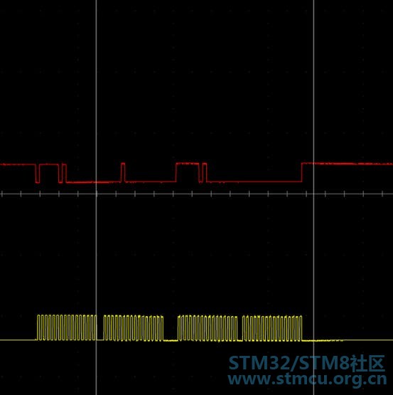
根据参考手册,诀窍是将寄存器DS(数据大小)配置为4位,并正确格式化DR寄存器中写入的数据。 
这就是为什么我更新了SPI(stm32-spi.adb)的默认驱动程序,如下面的写/读8位模式。 . ^% [) P" B, M6 T/ [( Y6 m3 b procedure Configure (This : in out SPI_Port; Conf : SPI_Configuration) isbegin ...- O% t1 M) D2 _4 V( |8 ` This.Periph.CR1.DFF := Conf.Data_Size = HAL.SPI.Data_Size_16b; This.Periph.CR2.DS := STM32_SVD.SPI.Size_4Bit; -- add this line4 O3 \2 M5 z Z) n9 B This.Periph.CR1.CPOL := Conf.Clock_Polarity = High; ... procedure Send_8bit_Mode (This : in out SPI_Port; Outgoing : HAL.SPI.SPI_Data_8b)6 b" B$ Q$ w, J/ }; z( g0 {# o( f is# n( ~/ H3 H; @; j) h Tx_Count : Natural := Outgoing'Length;' z& c9 T% ~4 K4 @3 n8 D y! e Index : Natural := Outgoing'First;" o% Q7 ^1 L" `. A; G+ } Tmp : UInt16; begin if Current_Mode (This) = Slave or else Tx_Count = 1 then Tmp := UInt16 ((Outgoing (Index) and 16#0F#))*256 + UInt16((Outgoing (Index) and 16#F0#))/16;0 L0 r" ?+ P, \- F; V- ?" y This.Periph.DR.DR := Tmp; Index := Index + 1;$ s7 o2 ^& F$ k: a8 [ Tx_Count := Tx_Count - 1;+ X g2 p4 s+ y1 w end if; ...$ f5 y) x/ ^4 H$ Z procedure Receive_8bit_Mode3 E, D1 o. E- D: r0 R* [ (This : in out SPI_Port; Incoming : out HAL.SPI.SPI_Data_8b) is* @. _# _: s. d8 ~: f0 V Generate_Clock : constant Boolean := Current_Mode (This) = Master; Tmp : Uint16; begin2 e# ?' q: j& r7 U; Q6 m for K of Incoming loop if Generate_Clock then4 ] n' U0 N" d0 d- j! }0 A This.Periph.DR.DR := 0;$ L0 E3 N: _7 Y9 t" g8 ]. p7 N/ { end if;7 A" a7 q0 D+ W' ? while Rx_Is_Empty (This) loop" F- L; l$ l1 G2 p! l& \ null;) \/ D- r3 _# B6 v; J+ ]( ]. h; E1 ]5 P end loop; Tmp := This.Periph.DR.DR; K := UInt8 (Tmp and 16#000F#)*16+ UInt8 ((Tmp and 16#0F00#)/256);" Z9 }5 Z! T, O U G. h ...7 Z. O# A4 M7 j7 K 3 y& E6 r; O1 C% x5 [/ |! X' f+ a$ M ) @/ ?( v5 N5 `# U5 I 8 F, s% d" E1 d, K / a" _; c- \1 ]" G 这样我获得了更好的时钟,BMI088寄存器中的读/写在8位模式下工作正常: 
% W' i3 a/ U* R( [$ I5 y' J: M 但还是不行: 因为我们需要在读取加速度计时(不是陀螺仪的情况)总是丢弃BMI088中的第一个接收字节。这就是为什么每次我进行读取时,我都必须先读取虚拟字节。通过此更新,我获得了更好的结果。 , z) e, N$ \+ h2 p) g 在BMI088.adb中: ---------- -- Read -- ---------- procedure Accel_Read (This : Six_Axis_Imu; Addr : Register; Data : out UInt8) is Status : SPI_Status; Tmp_Data : SPI_Data_8b (1 .. 1); begin SPI_Mode (This, Enabled => True); -- select the chip This.Port.Transmit (SPI_Data_8b'(1 => UInt8 (Addr) or ReadWrite_CMD), Status); if Status /= Ok then raise Program_Error; end if; This.Port.Receive (Tmp_Data, Status); -- dummy constraint BMI088 This.Port.Receive (Tmp_Data, Status); if Status /= Ok then raise Program_Error; end if; Data := Tmp_Data (Tmp_Data'First); SPI_Mode (This, Enabled => False); -- unselect the chip end Read; ---------------- -- Read_UInt8s -- ---------------- procedure Accel_Read_UInt8s (This : Six_Axis_Imu; Addr : Register; Buffer : out SPI_Data_8b; Count : Natural) is Index : Natural := Buffer'First; Status : SPI_Status; Tmp_Data : SPI_Data_8b (1 .. 1); begin SPI_Mode (This, Enabled => True); This.Port.Transmit (SPI_Data_8b'(1 => UInt8 (Addr) or ReadWrite_CMD), Status); if Status /= Ok then raise Program_Error; end if; This.Port.Receive (Tmp_Data, Status); -- dummy constraint BMI088 for K in 1 .. Count loop This.Port.Receive (Tmp_Data, Status); if Status /= Ok then raise Program_Error; end if; Buffer (Index) := Tmp_Data (Tmp_Data'First); Index := Index + 1; end loop; SPI_Mode (This, Enabled => False); end Read_UInt8s; # t* F/ E$ K& }( w& K0 |; T% m4 r最好从寄存器中读取加速数据。在下图中,我们仅表示SDO和时钟(SDI未表示,我只有2个探测......:'(): 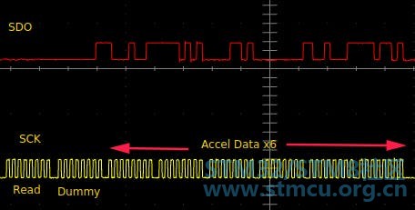
对于陀螺仪数据,虚拟字节没有问题。 这就是为什么必须要有Accel_Read和Gyro_Read不同的程序。 初始化BMI088的步骤 首先,您需要通过调用以下过程正确初始化SPI以与BMI088通信: 2 h; m3 B4 F6 M9 Q procedure Initialize_SPI1_For_BMI088 is# Q, ]3 ?# a; l- eConfig : GPIO_Port_Configuration; Config_SPI : SPI_Configuration;, ]# I3 o0 x% U! a begin% h: j' A+ t- J- S -- Enable the clocks Enable_Clock (IMU_SPI);& O! b* ~( V* Q1 ?* U Enable_Clock (SPI1_Points); Enable_Clock (IMU_SEL1); -- Configure the SPI IOs+ W& J, H# v. I' u8 N Config := (Mode => Mode_AF, AF => GPIO_AF_SPI1_5, AF_Speed => Speed_100MHz, AF_Output_Type => Push_Pull, Resistors => Floating);8 H6 r" R0 m" W( i Configure_IO(SPI1_Points, Config); -- Configure the SPI select chip IOs Config := (Mode => Mode_Out,& ?- U9 d: t1 {8 a1 y3 B! h# V Speed => Speed_25MHz,# r# K) _, t0 L+ m( g+ s Output_Type => Push_Pull, Resistors => Pull_Up); Configure_IO(IMU_SEL_Points, Config); -- Configure the SPI1 port4 Q! k4 r$ ?9 z! V a Config_SPI := (Direction => D2Lines_FullDuplex,6 K+ w% z) a5 B Mode => Master, Data_Size => HAL.SPI.Data_Size_8b,& N+ b9 x4 k4 E" s% D$ b Clock_Polarity => Low,, s/ @' l) S4 v0 }, u; Z% J" b Clock_Phase => P1Edge,6 @8 K* E3 J ]0 D Slave_Management => Software_Managed, Baud_Rate_Prescaler => BRP_328 U! g7 t; t8 z7 ]& \' X First_Bit => MSB,8 R* D0 o$ `: s1 n CRC_Poly => 7); Configure (IMU_SPI, Config_SPI);6 Q( E8 k6 M2 u$ J& B STM32.SPI.Enable (IMU_SPI); end Initialize_SPI1_For_BMI088;( w3 ~2 v1 N3 h0 j" Z8 } 然后按照以下步骤获取加速度计(寄存器和命令的值在数据表中定义,您可以在最后的驱动程序中找到它们): Bmi.Read(ACC_CHIP_ID_ADDR, Result);$ ~( ]1 g1 T3 g- w while Result /= ACC_CHIP_ID loop Bmi.Read(ACC_CHIP_ID_ADDR, Result);: B$ e: z: W# C- S9 E delay until Clock + Milliseconds (1); end loop;) q A" K* o+ b# G% ? ---- reset the accel Bmi.Write(ACC_SOFT_RESET_ADDR,ACC_RESET_CMD);9 \1 l$ v! y8 I2 U delay until Clock + Milliseconds (50);. D7 A" c- z+ e# r: j+ a Turn_ON(IMU_SEL1); delay until Clock + Milliseconds (5);2 S3 i* m; S5 h8 w: P7 p Turn_Off(IMU_SEL1);1 z" M! g9 C. J4 m0 |6 ?; ?! X4 J( p delay until Clock + Milliseconds (5); ---- enable the accel (rundandant to make sure it works) Bmi.Write(ACC_PWR_CNTRL_ADDR,ACC_ENABLE_CMD);/ j9 n/ Q m8 w) y, w! k delay until Clock + Milliseconds (50); * D2 \6 U9 [ s5 `# T5 g: G% X Bmi.Read(ACC_PWR_CNTRL_ADDR, Result);0 K% s% H7 v0 |" Y% Y+ ?# R while Result /= ACC_ENABLE_CMD loop: V+ U4 p; j1 J) f- U, Y" {) S Bmi.Write(ACC_SOFT_RESET_ADDR,ACC_RESET_CMD);# Z" v9 B& }& Q8 a5 z --delay until Clock + Milliseconds (1);" A, H+ A0 w0 S1 q4 X& S/ V" q Bmi.Write(ACC_PWR_CNTRL_ADDR,ACC_ENABLE_CMD); --delay until Clock + Milliseconds (50);+ C! E! ]. C0 D/ L* L Bmi.Read(ACC_PWR_CNTRL_ADDR, Result);* g8 ~- T, V! ~0 e4 u4 n4 c delay until Clock + Microseconds (4); O/ W( x( {: \: t5 z+ J, W end loop;0 E; V: \+ u3 B7 b$ [ ] ---- enter active mode Bmi.Write(ACC_PWR_CONF_ADDR,ACC_ACTIVE_MODE_CMD); delay until Clock + Milliseconds (5);+ p! B; I1 m" I* X, l Bmi.Read(ACC_PWR_CONF_ADDR, Result); while Result /= ACC_ACTIVE_MODE_CMD loop Bmi.Write(ACC_PWR_CONF_ADDR,ACC_ACTIVE_MODE_CMD); delay until Clock + Milliseconds (5);) w% t5 ]3 |/ m2 E7 @7 r Bmi.Read(ACC_PWR_CONF_ADDR, Result); {+ E n3 y3 X% F% C& P \ end loop;, u+ x, z6 s' L/ Z ---- set range 24G) m/ M5 k9 q- I- Q- z% G6 x Bmi.Write(ACC_RANGE_ADDR,RANGE_24G);- k' b8 W) [1 H& w6 |0 } delay until Clock + Milliseconds (1);6 t+ G6 U4 f5 ~0 s9 b6 F Bmi.Read(ACC_RANGE_ADDR, Result); while Result /= RANGE_24G loop Bmi.Read(ACC_RANGE_ADDR, Result); end loop; ---- set default ODR Bmi.Write(ACC_ODR_ADDR,ODR_1600HZ_BW_280HZ);, d& K% V) o' n+ q* h# r- J( g delay until Clock + Milliseconds (1); Bmi.Read(ACC_ODR_ADDR, Result);0 z; P2 L! T G* h. _% ^1 Q/ B while Result /= ODR_1600HZ_BW_280HZ loop Bmi.Read(ACC_ODR_ADDR, Result); end loop;6 w& c# }6 q3 F) p ---- check if there is an error Bmi.Read(ACC_ERR_CODE_ADDR, Result);6 I0 H6 i9 c8 `: L' O Q while Result /= 16#0# loop Bmi.Read(ACC_ERR_CODE_ADDR, Result); end loop;* c+ F9 D& z& C. z0 I ---- read the value1 [( A* w$ g V loop/ q5 `( |. Q8 x/ o+ } Bmi.Read_UInt8s(ACC_ACCEL_DATA_ADDR,Received,6);2 V% F8 y% J1 p delay until Clock + Microseconds (100);. _+ d1 U8 m( J) G' e end loop; 按照上面的步骤,我使用来自BMI088的SPI获取值。 / C- s1 n4 A; l1 _0 a( D步骤6:过滤和估计描述 应用几何变换: SuperIMU中IMU的配置不一样,它们被旋转(45°和90°): 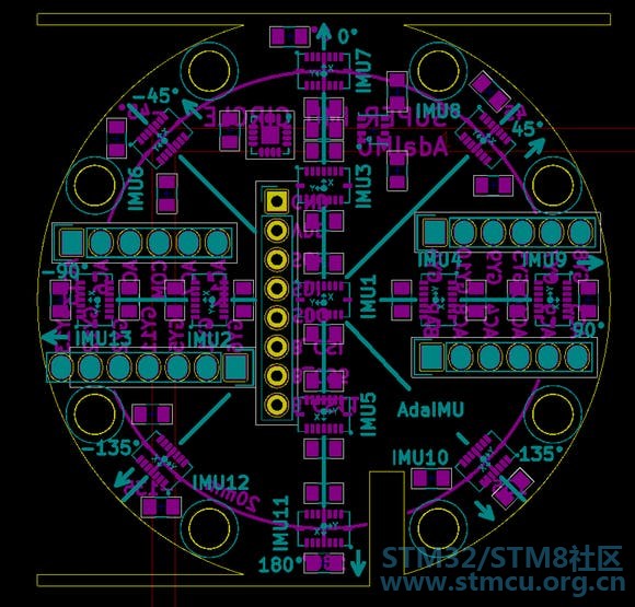
只有加速度X和Y受到旋转的影响。陀螺仪没有受到影响(转速是相对的)。 根据每个IMU位置完成旋转变换。旋转按以下过程编码: 6 N1 p" {3 o2 P5 b$ p -------------------- -- Accel rotation -- -------------------- Sqrt2 : constant Float := 1.41421356237; IMU_Alpha_Index : constant array (1 .. 3) of Integer := (1,3,7); IMU_Beta_Index : constant array (1 .. 2) of Integer := (5,11); IMU_Gamma_Index : constant array (1 .. 2) of Integer := (4,9); IMU_Delta_Index : constant array (1 .. 2) of Integer := (2,13); procedure ApplyIMURotation(i : Integer;xf : in out Float; yf : in out Float) is begin if i in IMU_Alpha_Index'range then null; -- we don't change elsif i in IMU_Beta_index'range then xf := -xf; yf := -yf; elsif i in IMU_Gamma_Index'range then xf := yf; yf := xf; elsif i in IMU_Delta_Index'range then xf := -yf; yf := -xf; elsif i = 8 then xf := Sqrt2*(-yf + xf); yf := Sqrt2*(yf + xf); elsif i = 6 then xf := Sqrt2*(-yf - xf); yf := Sqrt2*(-yf + xf); elsif i = 10 then xf := Sqrt2*(yf + xf); yf := Sqrt2*(yf - xf); elsif i = 12 then xf := Sqrt2*(yf - xf); yf := Sqrt2*(-yf - xf); end if; end; ' _) j7 G3 S% ~& J% y( F; e: u9 E. I [) m 使用范围: IMU的范围不同。每组IMU都有一个特定的范围: 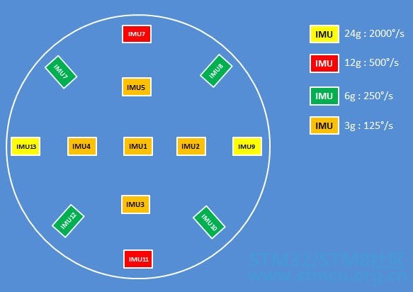
IMU分布,范围和名称 配置中使用的范围使用以下代码计算: -- Get the range to use --) ^9 D0 h4 r0 o0 m -------------------------- k# J5 H, m. }( w' [9 a9 S5 ` Range_3G_Index : constant array (1 .. 5) of Integer := (1,3,4,5,2);2 n) A; w% W5 U Range_6G_Index : constant array (1 .. 4) of Integer := (8,6,12,10); Range_12G_Index : constant array (1 .. 2) of Integer := (9,13);1 @, G8 I& e0 [ y8 n Range_24G_Index : constant array (1 .. 2) of Integer := (7,11); function GetAccelRangeConf(i : Integer) return Accel_Range is begin$ ?8 Q% D# U3 x7 E* { if i in Range_3G_Index'Range then return ACCEL_RANGE_3G;# B% H0 i+ m. S3 u' Q3 X- j elsif i in Range_6G_Index'Range then return ACCEL_RANGE_6G;2 `" r7 A# D$ k4 T elsif i in Range_12G_Index'Range then return ACCEL_RANGE_12G;0 h& ?7 w1 Y$ v* E# m9 b8 P elsif i in Range_24G_Index'Range then return ACCEL_RANGE_24G;& N1 q& U: o5 G else return ACCEL_RANGE_24G; end if; end; Range_125DPS_Index : constant array (1 .. 5) of Integer := (1,3,4,5,2); Range_500DPS_Index : constant array (1 .. 4) of Integer := (8,6,12,10); Range_1000DPS_Index : constant array (1 .. 2) of Integer := (9,13);- h7 Z8 A6 P! K. U Range_2000DPS_Index : constant array (1 .. 2) of Integer := (7,11); function GetGyroRangeConf(i : Integer) return Gyro_Range is begin if i in Range_125DPS_Index'Range then return GYRO_RANGE_125DPS; elsif i in Range_500DPS_Index'Range then( N) O: \! y/ O0 v% n$ k* d return GYRO_RANGE_500DPS;9 e0 y S( ?- q2 c( C* ?# t2 d+ d6 ? elsif i in Range_1000DPS_Index'Range then return GYRO_RANGE_1000DPS;" s$ j1 N( z5 A5 c elsif i in Range_2000DPS_Index'Range then7 f/ I% @2 i' ^; f/ S, L return GYRO_RANGE_2000DPS;# I! K" T' W# w$ v else return GYRO_RANGE_500DPS;6 {( n# @2 } }9 ?0 a+ v% ~+ _# e end if; end;+ l6 W3 ~2 B' }+ i2 S$ Y) V: E$ F 3 P. }' O6 z9 R5 Q 过滤代码: 根据每个IMU的配置范围对加速度和陀螺仪速率进行滤波。 权重使用以下代码计算: function GetAccelWeight(rng : Accel_Range; val : Sensor_Accel_Data) return Float is weight : Float := 0.0;6 A2 }" t! K. a( W4 g+ { refaccel : Float := 3.0; refrange : Float := 3.0;& ]# H1 b: V' b& W; J1 ?( o# }8 v- ^ begin% l q& _* y; x if ((abs(val(X))<3.0*0.95*G and abs(val(Y))<3.0*0.95*G and abs(val(Z))<3.0*0.95*G)) then refaccel := 3.0; elsif ((abs(val(X))<6.0*0.95*G and abs(val(Y))<6.0*0.95*G and abs(val(Z))<6.0*0.95*G)) then8 X; Z1 d2 X8 w! F+ M refaccel := 6.0; elsif ((abs(val(X))<12.0*0.95*G and abs(val(Y))<12.0*0.95*G and abs(val(Z))<12.0*0.95*G)) then5 H: K" ?) E( r: J2 U refaccel := 12.0; elsif ((abs(val(X))<24.0*0.95*G and abs(val(Y))<24.0*0.95*G and abs(val(Z))<24.0*0.95*G)) then1 c5 t; b4 N, ?; }5 v refaccel := 24.0; end if;% e, ?4 k4 N) O# `9 h0 u) M if rng = ACCEL_RANGE_3G then, @3 H. l5 T* C) A0 n; h' N X refrange := 3.0;# k) R+ X- l- W7 m' M Y6 U0 ~/ y+ O elsif rng = ACCEL_RANGE_6G then refrange := 6.0; elsif rng = ACCEL_RANGE_12G then# i8 K4 R4 a* D! e: v/ [ refrange := 12.0; elsif rng = ACCEL_RANGE_24G then; ?" ]2 A4 C% J2 Z3 f, e refrange := 24.0; end if; weight := refaccel / refrange;9 X" a' G6 B0 m* [; T6 W3 ~5 } if weight > 1.0 then return 0.0; end if; return refaccel/refrange;" m* K5 ? A. l4 U- u8 v end GetAccelWeight; function GetGyroWeight(rng : Gyro_Range; val : Sensor_Gyro_Data) return Float is weight : Float := 0.0;4 \6 c1 v2 `# r8 U refgyr : Float := 125.0;& v3 s; ~( i5 {, v0 B o refrange : Float := 125.0; begin, F+ {6 p# [# ^( Q if ((abs(val(X))<125.0*0.95 and abs(val(Y))<125.0*0.95 and abs(val(Z))<125.0*0.95)) then+ o3 M$ D. A- ]( l refgyr := 125.0; elsif ((abs(val(X))<250.0*0.95 and abs(val(Y))<250.0*0.95 and abs(val(Z))<250.0*0.95)) then refgyr := 250.0;+ T, b7 J& U8 T' m8 L U" ~! F0 O elsif ((abs(val(X))<500.0*0.95 and abs(val(Y))<500.0*0.95 and abs(val(Z))<500.0*0.95)) then4 [+ _; ?1 [' L7 F- D7 m9 \ refgyr := 500.0; elsif ((abs(val(X))<1000.0*0.95 and abs(val(Y))<1000.0*0.95 and abs(val(Z))<1000.0*0.95)) then! X7 T; \( v) t9 n refgyr := 1000.0; elsif ((abs(val(X))<2000.0*0.95 and abs(val(Y))<2000.0*0.95 and abs(val(Z))<2000.0*0.95)) then9 }( h# `7 F3 P) \2 ~! n. d6 D& N refgyr := 2000.0;* Y2 w! ^; T O" i/ R: ` end if; if rng = GYRO_RANGE_125DPS then) e( [- N; e& w" F# m: M refrange := 125.0;1 `& Y' H3 u3 y) G; T/ q0 F elsif rng = GYRO_RANGE_250DPS then refrange := 250.0; elsif rng = GYRO_RANGE_500DPS then refrange := 500.0;$ ]# o; t' D3 U. u- T elsif rng = GYRO_RANGE_250DPS then' k" b- p1 I2 d$ \2 N- U: T# ~ refrange := 1000.0; elsif rng = GYRO_RANGE_125DPS then refrange := 2000.0; end if; weight := refgyr / refrange; if weight > 1.0 then return 0.0;, L: K! e. d7 v R7 W) z' A end if;' @0 Z. @3 u# k' t) x- P6 y3 Y return refgyr/refrange; end GetGyroWeight;2 ~" ]7 ], v- s* N- [3 s+ Y p 9 d! h& a. s) s' x f7 q1 M * a# v: }3 H! S' A& Q3 o& Z 使用权重,加速度值是所有值的加权平均值: procedure FilterSuperIMU(facc : out Sensor_Accel_Data;4 h* i3 M9 b2 \0 @3 v* i, U. xfgyr : out Sensor_Gyro_Data) is sumacc : Sensor_Accel_Data; -- cumulated accel value" D$ m! ], c+ g1 G U sumgyr : Sensor_Gyro_Data; -- cumulated gyro value9 {8 q% |5 q$ S sumwacc : Float := 0.0; -- cumulated accel weight, K# @* u; i- @9 [ sumwgyr : Float := 0.0; -- cumulated accel weight7 \2 `( ^& A) W0 N! ]; c macc : Sensor_Accel_Data; -- measured accel value8 q S# T, G) ]* Z0 R mgyr : Sensor_Gyro_Data; -- measured accel value" W3 c/ t$ V. } mwacc : Float := 0.0; -- measured accel weight mwgyr : Float := 0.0; -- measured accel weight begin$ B9 K! l/ L# ?9 T7 X. n$ H. `1 l sumacc := NullAccelRate; sumgyr := NullGyroRate;* p, B! F* I- h1 ^& ]: J, v% z% j for i in Integer range 1 .. BMIs'Length loop " ^7 t% M% B: y4 q9 ?% P -- get accelerartion BMIs(i).ReadAccelRates(macc); X: @) y b) _0 h& J -- get weight according to the range mwacc := GetAccelWeight(BMIs(i).GetCurrentAccelRange, macc); -- apply 45° and inversion tranformation (geometry of the IMU) ApplyIMURotation(i,macc(X),macc(Y));. ^; ~" Z6 f8 f* K# H -- update the cumulated sum sumacc(X) := sumacc(X) + macc(X)*mwacc;0 Q4 H$ f& ^; V6 O sumacc(Y) := sumacc(Y) + macc(Y)*mwacc; sumacc(Z) := sumacc(Z) + macc(Z)*mwacc; sumwacc := sumwacc + mwacc; -- get the gyro rate0 ~2 J I4 L& H, `3 R2 \ -- we don't rotate the gyro rate, no need* w( _4 }: m& l. L BMIs(i).ReadGyroRates(mgyr);. [( X5 R1 G: }3 I! G. s -- compute the weight according to the range A5 E% f H5 s mwgyr := GetGyroWeight(BMIs(i).GetCurrentGyroRange, mgyr);' _0 m/ |% P, I8 e/ F -- update the cummulated weighted sum sumgyr(X) := sumgyr(X) + mgyr(X)*mwgyr; sumgyr(Y) := sumgyr(Y) + mgyr(Y)*mwgyr;$ r, O7 v- S/ h* t sumgyr(Z) := sumgyr(Z) + mgyr(Z)*mwgyr; -- sumwgyr := sumwgyr + mwgyr; end loop; facc(X) := sumacc(X) / sumwacc;: }9 ?2 d y5 h k, h+ l facc(Y) := sumacc(Y) / sumwacc; facc(Z) := sumacc(Z) / sumwacc; fgyr(X) := sumgyr(X) / sumwgyr;) I+ C1 u* O- u* E/ A0 C# M fgyr(Y) := sumgyr(Y) / sumwgyr;8 N+ g' o0 f0 L0 K4 } fgyr(Z) := sumgyr(Z) / sumwgyr; end FilterSuperIMU;4 `2 R2 O) S! @5 E# j9 a% f5 r " h# V+ c1 `# n) T5 m1 ~6 j 估算代码: 我用一个简单的互补滤波器来估算音高和滚动。我们从IMU获得加速度和陀螺仪速率数据。 代码在这里: 3 r5 ?/ B2 O# \* [- l5 _ procedure ComplementaryFilter(accelData : Sensor_Accel_Data; gyroData : Sensor_Gyro_Data) is pitchAccel : Float := 0.0; -- pitch computed from the accel rollAccel : Float := 0.0; -- roll computed from the accel begin -- integrate the gyroscope data estimatedPitch := estimatedPitch + gyroData(X)*dt; estimatedRoll := estimatedRoll + gyroData(Y)*dt; -- compensate the drift using the acceleration pitchAccel := Ada.Numerics.Elementary_Functions.Arctan(accelData(Y),accelData(Z))*RadToDeg; estimatedPitch := estimatedPitch * 0.98 + pitchAccel * 0.02; rollAccel := Ada.Numerics.Elementary_Functions.Arctan(accelData(X),accelData(Z))*RadToDeg; estimatedRoll := estimatedRoll * 0.98 + rollAccel * 0.02; null; end ComplementaryFilter; 4 c2 x! M z* C+ ^1 \! x 第7步:退役 使用OpenOCD 您也可以使用st-util,我已经在其他项目中完成了openocd的工作,这就是我使用它的原因。 重要(3小时获取时间评论):你需要在sudo模式下运行gnat gps,否则openocd无法访问usb端口。 安装OpenOCD 在ubuntu上使用OpenOCD的最佳方法是构建它。这样你就拥有了最新版本。我使用了gnu-mcu-eclipse/ openocd的最新版OpenOCD 。 要构建它很简单,只需确保安装了通用的C / C ++构建工具: 用于OpenOCD的配置: - 本地主机的端口为3333 - 我使用了来自openocd github 的stm32f 74discovery的配置文件。 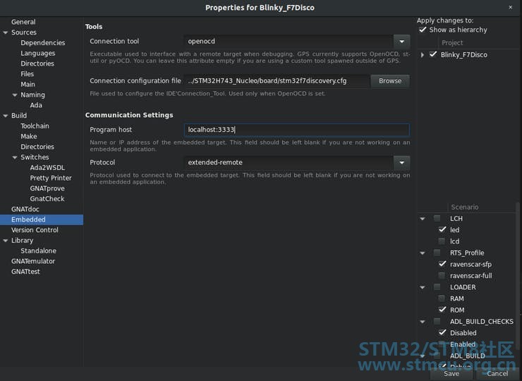
用于OpenOCD的配置 使用带有Analyzer2go的CYUSB3KIT-003对SPI进行分配 Analyzer2Go只是一个用于小预算的神奇工具。结合电路板CYUSB3KIT-003(45 $),您可以在200MHz采样率下使用功能强大的16x通道分析仪! 对于我的情况,与SPI / UART的交换低于10Mhz,并且读取Nucleo板的MCO(在100MHz下的PLL),这就足够了。 SPI测试 SPI的速度配置为STM32F746的6MHz(波特率DIV 32)。 我可以使用来自BMI088实例的SPI使用以下过程正确获取IMU运动数据: procedure ReadGyroRates (This : in out Six_Axis_Imu; Result : out Sensor_Gyro_Data);# J" I) L y) M 8 i5 ]! c$ T% G' R 第8步:PLL时钟测试:8 B) O. W+ l _; Q% B : l( m/ E1 o3 g4 T% Y ) K9 J& P/ o% Z' a" ` \ 在核板中,外部高速时钟(HSE)不是来自25MHz晶体(如Adacore内置STM32F746Disco),而是来自ST-Link芯片@ 8MHz。 经过数小时的调试后,我最终修改了adl_config.ads和s-bbbopa.ads(作为workarround)文件以设置HSE时钟的正确值。我终于为Nucleo-F746创建了一个新的BSP,而不是因为这种差异而使用stm32f746disco。 现在时钟正常运行,测量显示时间:4 ?+ |2 [( h, n7 w0 T4 s/ o6 ? 在调试模式下读取加速值需要35us 。 $ @6 V" G' l$ ]- u2 X) C( f! V. e( H 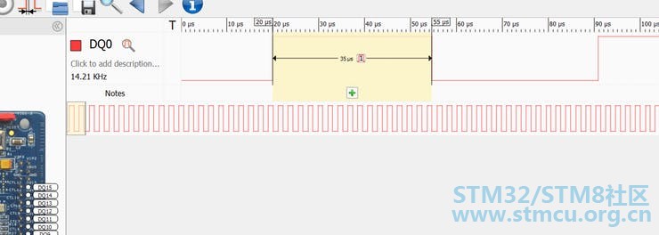
在从IMU读取值结束时,我使用流动代码切换引脚PG1: -- ReadAccelRates -- -------------------- procedure ReadAccelRates (This : in out Six_Axis_Imu; Result : out Sensor_Data)1 ~7 [! S- _+ N% d. K0 x is! s. s% C; [1 @5 x Received : SPI_Data_8b (1 .. 6); -- 2 bytes per axis AccelRates : BMI088.IMU_Rates;-- todo create AccelRate type C7 e/ T# j" ~4 O- a begin PG1.Set;7 @* E2 m2 l( ?3 Y N( f This.AccelRead_UInt8s(ACC_ACCEL_DATA_ADDR,Received,6);6 `) \ o1 d6 Z1 O1 z9 u AccelRates.X := As_IMU_Rates_Pointer (Received (1)'Address).all;( L0 D" C( J" [( {" X* [ AccelRates.Y := As_IMU_Rates_Pointer (Received (3)'Address).all; AccelRates.Z := As_IMU_Rates_Pointer (Received (5)'Address).all;& j/ C' f: e4 w Result(X) := Float (AccelRates.X) / 32768.0 * Accel_Range_MSS;* ^8 y: r) _0 Z% e9 m Result(Y) := Float (AccelRates.Y) / 32768.0 * Accel_Range_MSS;7 }4 q. |/ d. @- ~# I$ V/ A Result(Z) := Float (AccelRates.Z) / 32768.0 * Accel_Range_MSS; PG1.Clear;; M) S7 q4 V4 r+ }; A. z end ReadAccelRates;. u8 ^: u. v( D' n! ?; J' M( q Reading在调试模式下,完整的陀螺仪值需要34us 。 
+ q; z1 Q; R/ b, T* ^ -------------------8 r; X/ h9 @6 M -- ReadGyroRates -- ------------------- procedure ReadGyroRates (This : in out Six_Axis_Imu;4 ^4 L. E5 @/ s, K Result : out Sensor_Data)( s9 z' ^' H) E& E is Received : SPI_Data_8b (1 .. 6); -- 2 bytes per axis% ^' p/ C& f# {4 W1 K GyroRates : BMI088.IMU_Rates;-- todo create AccelRate type begin. Q* f. v& ~3 s/ A9 g PG1.Set; This.AccelRead_UInt8s(ACC_ACCEL_DATA_ADDR,Received,6);: d7 q7 r2 J" j; K1 k# s0 Z GyroRates.X := As_IMU_Rates_Pointer (Received (1)'Address).all; GyroRates.Y := As_IMU_Rates_Pointer (Received (3)'Address).all;3 q0 l- |3 Z- M' M& Z: X' O GyroRates.Z := As_IMU_Rates_Pointer (Received (5)'Address).all; Result(X) := Float (GyroRates.X) / 32768.0 * Gyro_Range_Rads; Result(Y) := Float (GyroRates.Y) / 32768.0 * Gyro_Range_Rads;! j2 N: {7 j8 P) n" E Result(Z) := Float (GyroRates.Z) / 32768.0 * Gyro_Range_Rads; PG1.Clear;# _3 t- K( u# Q3 y* Q2 W- U! `$ U end ReadGyroRates;' @) m+ B G% d" N+ @9 ?- Y Of 对于真实用例,我需要将编译模式设置为生产以进行正确的优化。 步骤9:使用UART绘制数据 为了可视化输出数据,我想使用UART在超级惊人的酷系列绘图仪中可视化它:https://github.com/CieNTi/serial_port_plotter 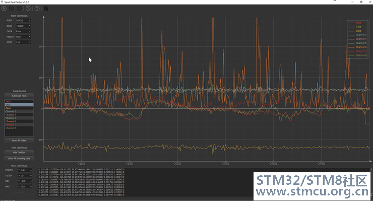
现在的问题是将Float转换为String ..以使用UART将其发送到Serial_Port_Plotter工具。 为此,我在这里使用神奇的单词'Img in Ada 将Float转换为String。然后我逐字节地将字符串发送到UART。 如果要发送一个值: - 发送“$” - 发送浮点值" {9 R' x8 e& l' ^3 C3 v$ H! m, O - 发送“;” 如果你想发送多个值: - 发送“$”开始 - 发送浮点数值1 * F/ M6 v3 _ m! s - 发送空格“” 1 K$ O0 y& Z4 Y* V/ @* n3 V ... - 发送浮点值i - 发送空格“” - 发送“;” 终止 为了能够向绘图仪发送加速度,我使用了以下代码: data_1B(0) := UInt8(36); -- '$'* X( B" v8 q& s' W( }( R UART_OUT.Transmit(data_1B,status); for ch of FixedFloat(AccelRates(X))'Img loop c := Character(ch);& m" r* v. U1 B1 j* U& |* z data_1B(0) := Character'Pos(c); UART_OUT.Transmit(data_1B,status);( M8 a: k9 Q& b( @; `5 r end loop;# g. H* W- u9 q, Y% Y4 K. [1 \ data_1B(0) := UInt8(59); -- ';'! c% h/ _' D/ G5 n" w& g) { UART_OUT.Transmit(data_1B,status); - W: w9 C. o+ t5 l7 y" `& u 结果非常令人满意,在下面的快照中我实时可视化Accelerometer(X)值: 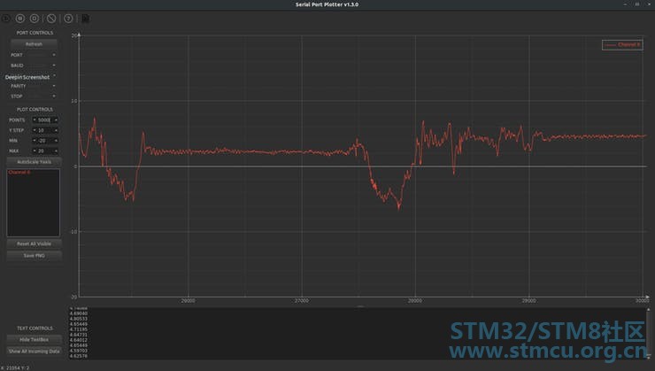
创建驱动程序后,该数据通过UART端口正确发送: 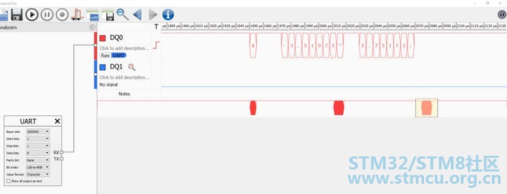
为UART制作驱动程序 不幸的是,在STM32F7器件中还没有UART驱动器(仅适用于STM32F4)。 要为UART创建驱动程序,我从STM32 F4 的stm32-usarts.ads/adb开始。我修改了文件以符合STM32 F7 的SVD 。我还要修改STM32-Device.ads/adb以包含STM32F7的UART / USART定义。 它适用于传输9或8位大小的字节。我没有测试它的DMA风格(因为从未做过  ) )! `0 ]& K' V3 {& F; a 代码广告: -------------------------------------------------------------------------------- -- -- Copyright (C) 2015-2016, AdaCore -- -- -- -- Redistribution and use in source and binary forms, with or without --9 u$ O, Z ~% ?8 Q7 [2 l -- modification, are permitted provided that the following conditions are --# @; ?4 V" ]5 j -- met: -- -- 1. Redistributions of source code must retain the above copyright --; a/ F) x8 ]( m9 _, n; e* h -- notice, this list of conditions and the following disclaimer. --4 D1 a& [( B+ U7 L; ] -- 2. Redistributions in binary form must reproduce the above copyright -- -- notice, this list of conditions and the following disclaimer in -- -- the documentation and/or other materials provided with the -- -- distribution. -- -- 3. Neither the name of STMicroelectronics nor the names of its --: E( D/ @8 Z- O6 T& B -- contributors may be used to endorse or promote products derived -- -- from this software without specific prior written permission. --8 f5 w; q( [* z2 b -- --* m5 q6 T" s* m0 r5 }- u% X- B$ D -- THIS SOFTWARE IS PROVIDED BY THE COPYRIGHT HOLDERS AND CONTRIBUTORS --) K# {3 A2 F2 G3 y Z -- "AS IS" AND ANY EXPRESS OR IMPLIED WARRANTIES, INCLUDING, BUT NOT --$ P+ p* l( p4 T: G( f" M8 b% B -- LIMITED TO, THE IMPLIED WARRANTIES OF MERCHANTABILITY AND FITNESS FOR -- -- A PARTICULAR PURPOSE ARE DISCLAIMED. IN NO EVENT SHALL THE COPYRIGHT -- -- HOLDER OR CONTRIBUTORS BE LIABLE FOR ANY DIRECT, INDIRECT, INCIDENTAL, -- -- SPECIAL, EXEMPLARY, OR CONSEQUENTIAL DAMAGES (INCLUDING, BUT NOT --# m2 q% P& F3 B9 l7 M -- LIMITED TO, PROCUREMENT OF SUBSTITUTE GOODS OR SERVICES; LOSS OF USE, --$ {4 {0 C, M- i* \+ s* ~6 D -- DATA, OR PROFITS; OR BUSINESS INTERRUPTION) HOWEVER CAUSED AND ON ANY -- -- THEORY OF LIABILITY, WHETHER IN CONTRACT, STRICT LIABILITY, OR TORT -- -- (INCLUDING NEGLIGENCE OR OTHERWISE) ARISING IN ANY WAY OUT OF THE USE --3 g) \$ x. z( K& `% n1 W* z5 P -- OF THIS SOFTWARE, EVEN IF ADVISED OF THE POSSIBILITY OF SUCH DAMAGE. -- -- --7 f5 _& Y1 P) G: L' E -- --+ v( p- D0 ^; S S: n4 v' f9 A2 D -- This file is based on: -- -- -- -- @file stm32f4xx_hal_usart.h --4 }7 R! s9 O( t# m+ q* A -- @author MCD Application Team -- -- @version V1.1.0 -- -- @date 19-June-2014 --: |$ c3 w) K) [8 Z( D. |9 x -- @brief Header file of USARTS HAL module. --' e. Y; \6 C" N" @& Q5 G2 [ -- --5 z) [) ~. r/ Y, \6 l" P -- COPYRIGHT(c) 2014 STMicroelectronics -- ------------------------------------------------------------------------------ -- This file provides register definitions for the STM32F4 (ARM Cortex M4F)# U0 ^( J. A# s# ^* s0 ~. e -- USART from ST Microelectronics. -- Note that there are board implementation assumptions represented by the6 a, @5 X6 ~) }1 x& A -- private function APB_Clock. with System;" s" ~1 s; L) }4 a. E, _3 B: P7 m with HAL.UART; use HAL.UART; private with STM32_SVD.USART; package STM32.USARTs is type Internal_USART is limited private;, y f. I. k4 p- n/ W( e type USART (Periph : not null access Internal_USART) is limited new HAL.UART.UART_Port with private; procedure Enable (This : in out USART) with# E7 k- C2 d; a Post => Enabled (This), Inline; procedure Disable (This : in out USART) with Post => not Enabled (This),9 v$ {; j' X0 a8 S Inline; function Enabled (This : USART) return Boolean with Inline;; D8 P1 i( r, ~3 U! t0 s0 h# l. q procedure Receive (This : USART; Data : out UInt9) with Inline;: j, g& j/ S: l; e6 W -- reads Device.DR into Data4 t# ?2 g- I% J0 X P5 L0 h0 ^, j function Current_Input (This : USART) return UInt9 with Inline; -- returns Device.DR procedure Transmit (This : in out USART; Data : UInt9) with Inline; function Tx_Ready (This : USART) return Boolean with Inline; function Rx_Ready (This : USART) return Boolean with Inline; type Stop_Bits is (Stopbits_1, Stopbits_2) with Size => 2;; Z$ \) p1 I' {0 F- ~ for Stop_Bits use (Stopbits_1 => 0, Stopbits_2 => 2#10#); procedure Set_Stop_Bits (This : in out USART; To : Stop_Bits); type Word_Lengths is (Word_Length_8, Word_Length_9); procedure Set_Word_Length (This : in out USART; To : Word_Lengths);5 j% v* R$ J( F" Q1 X type Parities is (No_Parity, Even_Parity, Odd_Parity);; w) Q; M8 E4 H procedure Set_Parity (This : in out USART; To : Parities); subtype Baud_Rates is UInt32;; ^- W" ?8 X# V0 O" X procedure Set_Baud_Rate (This : in out USART; To : Baud_Rates);* M- G; N4 Y y A* Q9 Y/ f type Oversampling_Modes is (Oversampling_By_8, Oversampling_By_16); -- oversampling by 16 is the default procedure Set_Oversampling_Mode: G* x8 {5 Z; {9 c2 s, Y' U (This : in out USART;/ b/ J/ n3 Q; l( M To : Oversampling_Modes); type UART_Modes is (Rx_Mode, Tx_Mode, Tx_Rx_Mode); procedure Set_Mode (This : in out USART; To : UART_Modes); type Flow_Control is (No_Flow_Control, RTS_Flow_Control,+ B; Z3 `9 ^0 U; O6 N CTS_Flow_Control, RTS_CTS_Flow_Control);& m% I# _; Z( t. H, P procedure Set_Flow_Control (This : in out USART; To : Flow_Control); type USART_Interrupt is (Parity_Error, Transmit_Data_Register_Empty,) C8 ^ b, ]+ M% w U0 d9 l Transmission_Complete,! l0 K" k- o% D1 D3 [7 \! [- d Received_Data_Not_Empty,4 ~% ^7 Q1 J4 j Idle_Line_Detection, Line_Break_Detection," q) [! A$ F5 T8 ?, b" B, w Clear_To_Send,; }5 A: |/ I. b$ g% Q9 K Error); procedure Enable_Interrupts (This : in out USART; Source : USART_Interrupt) with Post => Interrupt_Enabled (This, Source),* h* M1 x: w8 k8 i/ j Inline;% d# ]# y* Z$ E0 K& D procedure Disable_Interrupts (This : in out USART;6 l8 A1 y- \3 F& L) g' f Source : USART_Interrupt)" Z1 x. P. t R4 {, B- u, W with7 F& a7 @' d2 e4 [1 l6 f- K4 i Post => not Interrupt_Enabled (This, Source), Inline;8 v" b6 S! ]9 d, ] function Interrupt_Enabled (This : USART; Source : USART_Interrupt) return Boolean with Inline; type USART_Status_Flag is (Parity_Error_Indicated, Framing_Error_Indicated,5 s7 k( |( @( q/ I# V USART_Noise_Error_Indicated, Overrun_Error_Indicated, Idle_Line_Detection_Indicated,0 r2 ~' ], v! u& U0 J4 R" c Read_Data_Register_Not_Empty, Transmission_Complete_Indicated,: i9 j1 m' M9 K) R" B. D" v! y Transmit_Data_Register_Empty, Line_Break_Detection_Indicated, Clear_To_Send_Indicated); function Status (This : USART; Flag : USART_Status_Flag) return Boolean3 [- d7 }1 ]( O4 E4 f! @) } with Inline;/ d. x# A: V1 x! U2 M3 \, K procedure Clear_Status (This : in out USART; Flag : USART_Status_Flag)2 ^+ }7 f; F6 A$ d2 ~6 J$ p with Inline;! a- i2 P: K+ r procedure Enable_DMA_Transmit_Requests (This : in out USART) with Inline, Post => DMA_Transmit_Requests_Enabled (This); procedure Disable_DMA_Transmit_Requests (This : in out USART) with Inline, Post => not DMA_Transmit_Requests_Enabled (This);5 ^8 L3 r) w( E0 y ~ function DMA_Transmit_Requests_Enabled (This : USART) return Boolean with Inline; procedure Enable_DMA_Receive_Requests (This : in out USART) with, D. d8 Z/ j9 y9 F, a( s; ] Inline,- C- X6 C5 Q$ C' l Post => DMA_Receive_Requests_Enabled (This);! e3 r) C7 d2 T# ~0 w procedure Disable_DMA_Receive_Requests (This : in out USART) with F3 ?9 M. ^' }( G Inline, Post => not DMA_Receive_Requests_Enabled (This); function DMA_Receive_Requests_Enabled (This : USART) return Boolean with Inline; procedure Pause_DMA_Transmission (This : in out USART) renames Disable_DMA_Transmit_Requests; procedure Resume_DMA_Transmission (This : in out USART) with4 p+ D9 B" a% I6 x: i; k Inline,. Z1 c9 D' T4 B8 g# _! Q Post => DMA_Transmit_Requests_Enabled (This) and Enabled (This);0 g" I% I( P1 C6 c0 P procedure Pause_DMA_Reception (This : in out USART) renames Disable_DMA_Receive_Requests;1 D, N& n9 M4 W* i procedure Resume_DMA_Reception (This : in out USART) with% f: J3 }9 V+ Q( }# e; d, Z$ J+ R Inline, Post => DMA_Receive_Requests_Enabled (This) and0 r% l% f6 s8 u2 o; o2 H Enabled (This);! r' h5 Z8 H- Y! Z8 B8 D+ M: n1 t function Data_Receive_Register_Address (This : USART) return System.Address with9 m$ A$ |& l- P; q- ] Inline;5 I0 q x: v/ r! W% ~: } function Data_Transmit_Register_Address (This : USART) return System.Address with/ I1 l6 o1 y" @' Q6 P2 F7 _ Inline; -- Returns the address of the USART Data Register. This is exported -- STRICTLY for the sake of clients driving a USART via DMA. All other -- clients of this package should use the procedural interfaces Transmit -- and Receive instead of directly accessing the Data Register! -- Seriously, don't use this function otherwise. ----------------------------- -- HAL.UART implementation --/ V6 F) [% N; } ----------------------------- overriding0 b5 b: ?+ h- T) I) Z function Data_Size (This : USART) return HAL.UART.UART_Data_Size; overriding+ z/ @" d; \5 R( a" n7 k procedure Transmit (This : in out USART;3 f9 r; S# d2 g: m# g Data : UART_Data_8b;# Y" Q0 T% g: t$ a( `' z3 K) P- p3 ~ Status : out UART_Status; Timeout : Natural := 1000) with! x& \+ S0 \" e! n Pre'Class => Data_Size (This) = Data_Size_8b;' W( o3 q) I% u% r" M I# T& x+ G overriding procedure Transmit% h% n. q+ c" c G4 g (This : in out USART; Data : UART_Data_9b; Status : out UART_Status;$ r: T) e! a8 g4 _" C Timeout : Natural := 1000) with4 y5 l. [: G6 E% a$ @5 g Pre'Class => Data_Size (This) = Data_Size_9b;0 o% W2 Y7 P% S overriding3 M# @% u1 u' i+ Z+ K (This : in out USART; Data : out UART_Data_8b; Status : out UART_Status; Timeout : Natural := 1000) with Pre'Class => Data_Size (This) = Data_Size_8b; overriding procedure Receive (This : in out USART; Data : out UART_Data_9b; Status : out UART_Status; Timeout : Natural := 1000)$ Y- |" T$ [0 E p with Pre'Class => Data_Size (This) = Data_Size_9b; private function APB_Clock (This : USART) return UInt32 with Inline; -- Returns either APB1 or APB2 clock rate, in Hertz, depending on the' f9 i0 M$ D& ?! J, v7 ]; i -- USART. For the sake of not making this package board-specific, we assume -- that we are given a valid USART object at a valid address, AND that the -- USART devices really are configured such that only 1 and 6 are on APB2. -- Therefore, if a board has additional USARTs beyond USART6, eg USART8 on4 V- e: k" n0 A: r6 m5 P7 V% K) C -- the F429I Discovery board, they better conform to that assumption. -- See Note # 2 in each of Tables 139-141 of the RM on pages 970 - 972. O# S3 l. u) K* b7 F* c type Internal_USART is new STM32_SVD.USART.USART_Peripheral;- E3 J e8 Z5 b1 R! e type USART (Periph : not null access Internal_USART) is limited new HAL.UART.UART_Port with null record; end STM32.USARTs; , n/ \$ B. S% R & y1 k/ q k. V! [+ D O* s 代码adb: ------------------------------------------------------------------------------/ P) W0 m" j! a-- -- -- Copyright (C) 2015-2017, AdaCore -- -- --* d8 _1 h. o! t -- Redistribution and use in source and binary forms, with or without -- -- modification, are permitted provided that the following conditions are --3 Q9 K) v7 j8 g1 d2 N -- met: --& K8 C ~* S1 b6 M' m -- 1. Redistributions of source code must retain the above copyright -- -- notice, this list of conditions and the following disclaimer. -- -- 2. Redistributions in binary form must reproduce the above copyright -- -- notice, this list of conditions and the following disclaimer in --0 e# R& J0 ~6 `, W2 r -- the documentation and/or other materials provided with the -- -- distribution. --1 _! `# ^0 X1 O. K -- 3. Neither the name of STMicroelectronics nor the names of its --$ m* b& i- S* v# t9 R* V -- contributors may be used to endorse or promote products derived --9 q+ W) Y8 }6 y! w7 }7 w -- from this software without specific prior written permission. --* {* M& x4 k4 _, r7 i" x/ H o, F. o -- -- -- THIS SOFTWARE IS PROVIDED BY THE COPYRIGHT HOLDERS AND CONTRIBUTORS --+ @ d: \8 K, k4 [. r7 `4 ~ -- "AS IS" AND ANY EXPRESS OR IMPLIED WARRANTIES, INCLUDING, BUT NOT --) s: z1 f( A/ V -- LIMITED TO, THE IMPLIED WARRANTIES OF MERCHANTABILITY AND FITNESS FOR -- -- A PARTICULAR PURPOSE ARE DISCLAIMED. IN NO EVENT SHALL THE COPYRIGHT -- -- HOLDER OR CONTRIBUTORS BE LIABLE FOR ANY DIRECT, INDIRECT, INCIDENTAL, -- -- SPECIAL, EXEMPLARY, OR CONSEQUENTIAL DAMAGES (INCLUDING, BUT NOT -- -- LIMITED TO, PROCUREMENT OF SUBSTITUTE GOODS OR SERVICES; LOSS OF USE, --2 ]( @1 V' J" f; a9 L -- DATA, OR PROFITS; OR BUSINESS INTERRUPTION) HOWEVER CAUSED AND ON ANY -- S: q: m8 B, K1 u -- THEORY OF LIABILITY, WHETHER IN CONTRACT, STRICT LIABILITY, OR TORT -- -- (INCLUDING NEGLIGENCE OR OTHERWISE) ARISING IN ANY WAY OUT OF THE USE --& ^: F; h6 d$ l9 F -- OF THIS SOFTWARE, EVEN IF ADVISED OF THE POSSIBILITY OF SUCH DAMAGE. --# w6 Q8 {+ E+ U& p- r0 z# s -- -- -- --! J8 B% r$ `# A1 W+ E6 | o -- This file is based on: --4 L# p8 Z6 }3 S8 ]* G -- --% i& P% W1 v5 W1 Y. Q, ^1 \" _ -- @file stm32f4xx_hal_usart.c --6 p2 D4 Z7 }; j% Y; z: | -- @author MCD Application Team -- -- @version V1.1.0 -- -- @date 19-June-2014 -- -- @brief USARTS HAL module driver. -- -- --3 Z9 _* T2 [" K9 p: Z9 R, w% Y; T -- COPYRIGHT(c) 2014 STMicroelectronics --- C0 z* b$ l, \4 ?! Q( p0 t ------------------------------------------------------------------------------ with System; use System; H% Z& x1 p5 G4 `8 [ with STM32_SVD.USART; use STM32_SVD, STM32_SVD.USART;. A( N' e/ s. e9 c$ J with STM32.Device; use STM32.Device;$ G- p1 Q7 e: B& j package body STM32.USARTs is' j/ r6 Q, m. q( H0 n9 p* R0 s N --------------- -- APB_Clock -- --------------- function APB_Clock (This : USART) return UInt32 is Clocks : constant RCC_System_Clocks := System_Clock_Frequencies;6 n, h- {4 F0 S0 p$ d! V begin* s1 W& v3 U/ z: R" H if This.Periph.all'Address = USART1_Base& ` k% J: |# v. c or; H' X" j/ p* c" F This.Periph.all'Address = USART6_Base then+ N# W j; A9 ` Y3 k0 M& @ return Clocks.PCLK2; else return Clocks.PCLK1;! m1 R4 U# N7 S* Q- x end if;9 Y3 L) C. T7 S: Q% C end APB_Clock;0 V- r P3 h- E( Z, k ------------ -- Enable -- ------------ procedure Enable (This : in out USART) is begin This.Periph.CR1.UE := True; L3 X7 W# t$ y# X3 |5 C, ?; P end Enable; -------------% j6 N; h6 Q* m6 X' O -- Disable --1 ?. }6 ?) ^2 D3 ^7 l1 c: V$ H -------------# j% _$ D ]: [* j( d: i; V N procedure Disable (This : in out USART) is% s3 I$ M- V+ Z& o$ Y begin This.Periph.CR1.UE := False;& @# A2 j- F. `' T* p+ S0 R end Disable;" U9 W4 b7 D4 | ------------- -- Enabled -- -------------/ q! O5 t4 N- u n function Enabled (This : USART) return Boolean is (This.Periph.CR1.UE);) [6 M5 i" k4 M6 o6 |+ t -------------------- }( O2 x8 F) {( O4 q -- Set_Stop_Bits -- ------------------- procedure Set_Stop_Bits (This : in out USART; To : Stop_Bits) is begin. ~7 Y; [! i1 R" C This.Periph.CR2.STOP := Stop_Bits'Enum_Rep (To);! f0 m! s- T: B, Z) |" }3 p end Set_Stop_Bits; --------------------- -- Set_Word_Length --" K$ U9 _" N2 r0 d5 F# G* _2 O5 g- D ---------------------: r9 O# P; C+ h; N procedure Set_Word_Length. d4 | R, l# T" E (This : in out USART;( c5 L( J7 T' T& M- e To : Word_Lengths) is: t( O3 V! n$ X" T, V2 Q begin! W6 Q( @1 t1 W7 X) f1 q' z, R This.Periph.CR1.M0 := To = Word_Length_9;6 _; c; ~4 w: E1 R end Set_Word_Length;: F$ V1 f& G( H1 P/ ? ----------------9 k5 Y2 V1 g$ ~- i b: T* k -- Set_Parity -- ----------------- S @/ @: N& n procedure Set_Parity (This : in out USART; To : Parities) is7 |2 d' y; S2 {2 D6 Z begin9 Z3 S7 e* l" E) f5 n" T case To is when No_Parity =>" M# R7 d" r, w7 [ This.Periph.CR1.PCE := False;0 d" Z9 K+ A. Z) h5 L* q( {+ {. L& H This.Periph.CR1.PS := False; when Even_Parity => This.Periph.CR1.PCE := True; This.Periph.CR1.PS := False; when Odd_Parity =>$ Y: o* X9 Z( z) V- {' ~8 \ This.Periph.CR1.PCE := True; This.Periph.CR1.PS := True;& I+ g8 k: j7 N end case;: \) Q, E( ^0 b3 z end Set_Parity; ------------------- -- Set_Baud_Rate --8 @9 ^9 R$ g7 D! ~5 X ------------------- procedure Set_Baud_Rate (This : in out USART; To : Baud_Rates) is Clock : constant UInt32 := APB_Clock (This);& Q$ Z' W/ S1 x) `# s2 b# p( b Over_By_8 : constant Boolean := This.Periph.CR1.OVER8;$ D; u- j5 |7 \8 ~- \- } Int_Scale : constant UInt32 := (if Over_By_8 then 2 else 4);% o: t5 H, a! H" X! C Int_Divider : constant UInt32 := (25 * Clock) / (Int_Scale * To);& C6 T/ q& ]7 } Frac_Divider : constant UInt32 := Int_Divider rem 100; begin -- the integer part of the divi2 l: P6 `4 R8 V if Over_By_8 then This.Periph.BRR.DIV_Fraction :=, m( @( G: |1 O% ?) } i) S, K: [ BRR_DIV_Fraction_Field (((Frac_Divider * 8) + 50) / 100 mod 8);8 i4 M, G# j q$ W& a else1 c2 m/ ]) J% Q. i% O4 C0 Z. a k This.Periph.BRR.DIV_Fraction := BRR_DIV_Fraction_Field (((Frac_Divider * 16) + 50) / 100 mod 16); end if; This.Periph.BRR.DIV_Mantissa := BRR_DIV_Mantissa_Field (Int_Divider / 100); end Set_Baud_Rate;# Z! |& ]+ F4 ?3 ?) A --------------------------- -- Set_Oversampling_Mode -- --------------------------- procedure Set_Oversampling_Mode: ]* B, C+ V8 E; z6 f" Q (This : in out USART; To : Oversampling_Modes) is% o" U# D; ~8 p begin, l7 ?( B4 g) @( W This.Periph.CR1.OVER8 := To = Oversampling_By_8; end Set_Oversampling_Mode;$ h: o4 g/ Q& b- }" {2 ` -------------- -- Set_Mode --+ M8 X. _& W0 V8 N -------------- procedure Set_Mode (This : in out USART; To : UART_Modes) is begin This.Periph.CR1.RE := To /= Tx_Mode; This.Periph.CR1.TE := To /= Rx_Mode; end Set_Mode; ----------------------& j, \& s5 G4 H; `) g' z -- Set_Flow_Control -- ----------------------* P; }. i5 ?) |8 d7 n9 L procedure Set_Flow_Control (This : in out USART; To : Flow_Control) is4 \' `0 s/ y' e( h# g% d( F begin3 q* |# m, `7 v5 B0 |1 E case To is when No_Flow_Control =># b! x+ G* ^1 l, N6 K/ y This.Periph.CR3.RTSE := False;$ i0 Z, ~5 \0 R This.Periph.CR3.CTSE := False; when RTS_Flow_Control => This.Periph.CR3.RTSE := True; This.Periph.CR3.CTSE := False;' w" U: a) V9 m/ W% q. t( M when CTS_Flow_Control => This.Periph.CR3.RTSE := False;7 K$ S2 b( e; F ?6 Y, L This.Periph.CR3.CTSE := True; when RTS_CTS_Flow_Control => This.Periph.CR3.RTSE := True; This.Periph.CR3.CTSE := True; end case; end Set_Flow_Control;0 F( Z8 y _2 m5 L2 R --------- -- Put -- ---------, Z% d' A/ [; }7 [ procedure Transmit (This : in out USART; Data : UInt9) is+ I8 v' o! c f- B) ` begin2 D1 b: `% b6 p: z2 D2 y This.Periph.TDR.TDR := TDR_TDR_Field (Data); end Transmit; ---------0 B: I" J+ q1 `' ?$ L9 l -- Get -- --------- procedure Receive (This : USART; Data : out UInt9) is begin9 q1 W. y. U; U! x! o& S: ]9 ~7 I Data := Current_Input (This);; ]' U; j7 W) g2 ?' i end Receive; ------------------- -- Current_Input --0 l; {7 w, [1 Z# G1 e3 X ------------------- function Current_Input (This : USART) return UInt9 is (Uint9 (This.Periph.RDR.RDR));$ f5 J `* c: g7 { -------------- -- Tx_Ready --; P3 h& Z; C& v4 Y -------------- function Tx_Ready (This : USART) return Boolean is( a, v$ H0 k3 x! a begin2 P( L; e+ M0 N& B) p# D return This.Periph.ISR.TXE; end Tx_Ready; --------------* o3 B( g# }1 @* K1 |7 N -- Rx_Ready -- -------------- function Rx_Ready (This : USART) return Boolean is; G3 ?4 p% V/ D2 ?0 R6 }* H D begin- F* |2 E! _4 ?) t return This.Periph.ISR.RXNE; end Rx_Ready; ------------ -- Status --- L" _# `0 X, ]7 ~8 J ------------/ p. k8 j& J4 J2 v$ _$ P function Status (This : USART; Flag : USART_Status_Flag) return Boolean is begin case Flag is2 }7 {$ x" F! b" a; v when Parity_Error_Indicated => return This.Periph.ISR.PE;3 j9 f3 {/ x0 h- n+ h1 W$ y when Framing_Error_Indicated => return This.Periph.ISR.FE;/ q5 n) j. @6 `. T& n% i" ~ when USART_Noise_Error_Indicated =>9 u4 d6 J2 U, _2 L) [9 A+ ^7 f$ t return This.Periph.ISR.NF; when Overrun_Error_Indicated => return This.Periph.ISR.ORE; when Idle_Line_Detection_Indicated => return This.Periph.ISR.IDLE;5 D2 J) ?/ j) } when Read_Data_Register_Not_Empty =>0 ^0 ]+ r- ?+ F$ F3 k0 l2 T return This.Periph.ISR.RXNE; when Transmission_Complete_Indicated => return This.Periph.ISR.TC;( Y3 Q* u" b7 U. q8 g when Transmit_Data_Register_Empty => return This.Periph.ISR.TXE;. H. f( {- q ~" o+ G$ A when Line_Break_Detection_Indicated => return This.Periph.ISR.LBDF; when Clear_To_Send_Indicated => return This.Periph.ISR.CTS; end case; end Status;7 d8 ?! X/ K9 o2 C ------------------ -- Clear_Status --! w3 T* A+ T4 t. b ------------------ procedure Clear_Status (This : in out USART; Flag : USART_Status_Flag) is begin case Flag is4 u/ f+ D% A, d" n" Q' M when Parity_Error_Indicated => This.Periph.ISR.PE := False;" E, K: P* d& p when Framing_Error_Indicated => This.Periph.ISR.FE := False; when USART_Noise_Error_Indicated =>0 K* G4 ?3 {- l# I& Q$ i8 e This.Periph.ISR.NF := False;% D9 T3 b# z; w3 `1 U: l( i' i2 \ when Overrun_Error_Indicated => This.Periph.ISR.ORE := False; when Idle_Line_Detection_Indicated => This.Periph.ISR.IDLE := False;8 ^- Y5 H* L% [$ G6 u when Read_Data_Register_Not_Empty => This.Periph.ISR.RXNE := False;# @/ H v& c1 h" ^# ]4 Z when Transmission_Complete_Indicated => This.Periph.ISR.TC := False; when Transmit_Data_Register_Empty => This.Periph.ISR.TXE := False;8 i/ g/ a" \" w4 s/ U O5 Y when Line_Break_Detection_Indicated => This.Periph.ISR.LBDF := False; when Clear_To_Send_Indicated =>! d% \, e" L. n" a/ K9 C) x This.Periph.ISR.CTS := False;; }: S: m) n8 J3 J: ? end case; end Clear_Status;' V' U' J. S. H" M. T) x -----------------------9 s+ f' F% j: m8 Y- w: W4 G, m -- Enable_Interrupts -- ----------------------- procedure Enable_Interrupts( X# z) D' e( |' | (This : in out USART; Source : USART_Interrupt)" m+ ], O, c6 M6 E) L' u1 B# o is begin# Y$ N/ M; u, L& @4 X' V case Source is when Parity_Error =>( P) a" s. g$ Z- }; z This.Periph.CR1.PEIE := True;6 M' s& U* t0 J2 e8 Y& `$ L when Transmit_Data_Register_Empty =>) d% A; Y1 X" @0 ^) m1 r! l. Q This.Periph.CR1.TXEIE := True;5 S: _6 y" V9 Z+ p/ _ when Transmission_Complete => This.Periph.CR1.TCIE := True; when Received_Data_Not_Empty =>: h$ l$ ?% m- n9 M2 ~4 R* C This.Periph.CR1.RXNEIE := True; x+ l0 t* e+ J( l. C. d: X when Idle_Line_Detection =>7 x* j$ y4 ?' G This.Periph.CR1.IDLEIE := True; when Line_Break_Detection => This.Periph.CR2.LBDIE := True;" u# [: E4 ~# y4 h6 \) z# e when Clear_To_Send =>3 N5 g8 z- x/ G h4 n5 R+ b This.Periph.CR3.CTSIE := True; when Error => This.Periph.CR3.EIE := True;5 Q* Q2 M6 c& C0 ?( B# B5 H5 Y: b end case;& z- x8 v* v: n5 R end Enable_Interrupts;8 T- M: {3 d' `) K! }% X ------------------------- B# f; {5 o9 A+ w1 }5 {, x+ W, j -- Disable_Interrupts -- ------------------------ E3 l* C8 g& {* D* c+ E. T procedure Disable_Interrupts" T' {' ]( a4 z; C" v8 x (This : in out USART; Source : USART_Interrupt)7 D: D1 {9 H/ l: I0 ^" D is begin case Source is when Parity_Error => This.Periph.CR1.PEIE := False;8 Q6 o* o% E0 {2 o% ?* w2 w when Transmit_Data_Register_Empty => This.Periph.CR1.TXEIE := False;) L( j; }5 s; Z( t3 P& Z when Transmission_Complete =>6 ^+ s- ~% X( V, G" h This.Periph.CR1.TCIE := False; when Received_Data_Not_Empty =>" a. A" X- t5 k- {. i This.Periph.CR1.RXNEIE := False; when Idle_Line_Detection => This.Periph.CR1.IDLEIE := False;6 N$ S9 j3 r% x when Line_Break_Detection => This.Periph.CR2.LBDIE := False;7 L$ S. v- j3 j# a when Clear_To_Send => This.Periph.CR3.CTSIE := False;6 c( Y G# b9 ~: b3 L# }( b when Error =>: y; g# Q9 Q h( ? This.Periph.CR3.EIE := False; end case; end Disable_Interrupts;& D9 _$ |) V2 D/ u ----------------------- -- Interrupt_Enabled -- -----------------------! l. @ N# y" v& P# N function Interrupt_Enabled: o; c, n9 }% M' w/ e% A/ w (This : USART; Source : USART_Interrupt)4 M: O1 N! {; L5 h7 k/ z3 _ return Boolean7 H# L0 |1 x; g is begin0 |, x, i5 `& ? ^" }" s case Source is8 H/ f( g/ w: k U) O7 j when Parity_Error => return This.Periph.CR1.PEIE; when Transmit_Data_Register_Empty => A# c8 b, H3 S4 ` O, B$ T: T return This.Periph.CR1.TXEIE; when Transmission_Complete => return This.Periph.CR1.TCIE; when Received_Data_Not_Empty =>. W' e; M) I, c, `9 g return This.Periph.CR1.RXNEIE; when Idle_Line_Detection =>! K! ] C2 M1 r) _6 E, p return This.Periph.CR1.IDLEIE;5 ?: T: W, ^+ ?5 [' r4 o when Line_Break_Detection =>- h4 x' C' h3 t' d7 Y return This.Periph.CR2.LBDIE; when Clear_To_Send =>( m) T$ G6 Q D return This.Periph.CR3.CTSIE;; w3 l4 V i9 z' W when Error => return This.Periph.CR3.EIE; end case;$ m1 `7 f3 k$ `6 u end Interrupt_Enabled;0 {0 A4 ?5 i) U' N% h% E( N, v$ D ----------------------------------" `6 Y# F) Y8 }- S/ y' \ -- Enable_DMA_Transmit_Requests -- ---------------------------------- procedure Enable_DMA_Transmit_Requests (This : in out USART) is7 W2 A% c% ?& ?$ i6 q begin This.Periph.CR3.DMAT := True; end Enable_DMA_Transmit_Requests; ---------------------------------! G9 ]4 ?1 w# ^ -- Enable_DMA_Receive_Requests -- --------------------------------- procedure Enable_DMA_Receive_Requests (This : in out USART) is2 q% k( W+ y$ \5 h( z: d3 y8 D begin This.Periph.CR3.DMAR := True; end Enable_DMA_Receive_Requests;. N8 ~9 N! W* i# Q/ ]9 k7 y ----------------------------------- -- Disable_DMA_Transmit_Requests --6 y' [9 n% y3 M5 s ----------------------------------- procedure Disable_DMA_Transmit_Requests (This : in out USART) is begin This.Periph.CR3.DMAT := False;; M7 p1 V: k+ |' a* e1 o# ~1 g end Disable_DMA_Transmit_Requests; ----------------------------------) W6 |6 Q+ C3 G% h4 ~6 Q -- Disable_DMA_Receive_Requests --# M7 p, j( C8 z1 m3 l- ? ---------------------------------- procedure Disable_DMA_Receive_Requests (This : in out USART) is1 B ^: q: L! x- @& S1 | begin This.Periph.CR3.DMAR := False; end Disable_DMA_Receive_Requests;6 X& ?( ^' z$ I4 \4 X( U6 P5 e6 v ----------------------------------- -- DMA_Transmit_Requests_Enabled --4 v2 ]5 e/ \! ?) k* T( W -----------------------------------" H; B& r, x" T/ M function DMA_Transmit_Requests_Enabled (This : USART) return Boolean is* u$ D: n+ U) Y( G (This.Periph.CR3.DMAT); ---------------------------------- -- DMA_Receive_Requests_Enabled --1 `$ @8 F/ c5 y7 i' y, m- z6 | ----------------------------------# x, e4 J7 E5 H7 ?% u2 Y: }8 T function DMA_Receive_Requests_Enabled (This : USART) return Boolean is (This.Periph.CR3.DMAR); -----------------------------6 |+ J q/ y; O( ^- ?: j -- Resume_DMA_Transmission --' l! a: y& u2 t% X$ e. X9 j* Y/ l5 U9 S& z ----------------------------- procedure Resume_DMA_Transmission (This : in out USART) is% g% F6 d( P: I% w1 A begin5 ]! ]; a% w, l' F* X8 \1 t Enable_DMA_Transmit_Requests (This);+ i, f% |- B! e2 o2 f if not Enabled (This) then Enable (This);. E; M! r0 C) F9 W, z8 g0 @2 [1 c; ~ end if;. o" m; _! W6 I4 ?, [% h end Resume_DMA_Transmission; -------------------------- -- Resume_DMA_Reception --% F3 D$ C: w% d G1 c$ I --------------------------, Z+ M- q9 v+ r: \; u) M procedure Resume_DMA_Reception (This : in out USART) is begin$ d5 b/ X2 [8 Y% c Enable_DMA_Receive_Requests (This);3 Z" H0 }! b) n E' M if not Enabled (This) then Enable (This); end if; end Resume_DMA_Reception;0 h3 Y$ b( _3 c" H; X& | ---------------------------4 @' {+ i% `) O) F0 f3 \4 U @ -- Data_Register_Address -- ---------------------------) X- ~. \4 b: H W% @; O+ } function Data_Receive_Register_Address (This : USART) return System.Address is1 o$ R. q0 \' k2 k9 c (This.Periph.RDR'Address);2 P* T7 n& ?7 P& e# | --------------------------- -- Data_Register_Address -- ---------------------------: N9 g1 J4 Z, v, @9 e* o7 [1 q8 L function Data_Transmit_Register_Address (This : USART) return System.Address is (This.Periph.TDR'Address);, T0 A2 w. {" R7 E* e( p" P2 F, V6 l ---------------, n: B* c9 k3 I) e -- Data_Size --: x3 g$ F# }' X ---------------/ x4 c7 ]+ A& S4 N overriding6 @2 c( I" z! O+ `( w0 M1 | function Data_Size (This : USART) return HAL.UART.UART_Data_Size is# Y2 u s' X% }9 O3 @ begin if This.Periph.CR1.M0 then- H% p7 t9 k: J$ F8 c$ ?) v9 B return Data_Size_9b; else" Q# t3 ^8 q( h return Data_Size_8b; end if;5 ?5 o, f0 n5 \4 v: w P end Data_Size; --------------) g( M) R" G. E* h/ Q& s -- Transmit --0 F# I, ]7 w z7 n8 M R6 Y --------------+ E- R7 i2 m& L% r" W overriding) v/ u0 K4 C+ j! E procedure Transmit (This : in out USART;* c4 _. ^0 v$ w* R' v( B& Z Data : UART_Data_8b;7 a' o# @0 @$ O4 ^0 v Status : out UART_Status; Timeout : Natural := 1000) is pragma Unreferenced (Status, Timeout);6 J x4 f9 e1 n* v. z w begin for Elt of Data loop loop8 ?0 j/ ]- F3 K' `4 g) d exit when This.Tx_Ready;0 k0 f5 z, d) e+ E: _1 ^& ~ end loop; This.Transmit (UInt9 (Elt)); end loop; Status := Ok;6 J# q" w% p+ t4 ^9 p9 g5 P/ ? end Transmit; --------------, ?( i3 L) W v5 r% K: O -- Transmit -- --------------* k& P0 E. p2 A; A# I overriding procedure Transmit (This : in out USART; Data : UART_Data_9b;4 `- _' i1 Z0 `7 c3 O# o. j; U& U. M Status : out UART_Status; Timeout : Natural := 1000) is pragma Unreferenced (Status, Timeout);# `5 ?9 ] a$ r& j4 g0 f! k X9 B begin. p, {6 O% a8 F for Elt of Data loop! i# x" \" ~$ t( ~2 s7 \1 P& w loop6 I% @- ], p2 L* A, x2 T$ ] exit when This.Tx_Ready; end loop;4 y9 r' Z7 d' Q: d+ B This.Transmit (Elt);* a, i! Y" _+ a- T end loop; Status := Ok; end Transmit;# h2 R6 W$ t# u1 c. ?' d0 z: g- x -------------( O$ f; ], u( i -- Receive -- -------------2 x6 [. r( u% G4 w overriding0 ]$ ~/ d0 Y- p0 C$ y' z+ n* v procedure Receive0 m+ s& \% _8 O% ^% s) C% ]! @; f! M (This : in out USART;; H" B0 q( p3 z" f Data : out UART_Data_8b;$ d/ Q( {& f! d( g/ l Status : out UART_Status;1 s9 i. F# ~6 G/ H I Timeout : Natural := 1000) is/ b, t6 @$ R5 f" M. V% L& e pragma Unreferenced (Status, Timeout);/ M* P/ g" d" g- Z begin; v6 D8 r( n9 W for Elt of Data loop loop exit when This.Rx_Ready; end loop; This.Receive (UInt9 (Elt));/ S6 l& n* I: t2 o! b2 A ]; I end loop;0 O0 f" O( x+ m3 _1 Q9 @8 p Status := Ok;4 m1 i% L; j/ Q) ^4 T0 @2 X end Receive; -------------0 Y4 k4 {+ J$ r6 V* Z6 ]5 W$ ^ -- Receive -- -------------4 G. C& k# P1 d6 f6 Y overriding/ @. q. d0 e, Z# Y/ k2 Y1 E procedure Receive (This : in out USART;3 F) v" j9 Y' p* Z Data : out UART_Data_9b;) |8 I1 ^' Q( G& N, }( I. ~4 l% h7 C Status : out UART_Status; Timeout : Natural := 1000) is6 J% a. D+ P6 |1 T6 E pragma Unreferenced (Status, Timeout);( Y' J/ m5 j# \+ w! h begin/ O5 v, J& Q) v3 v" o9 i0 J g8 h for Elt of Data loop loop! |+ F% Z1 C: B) E) p exit when This.Rx_Ready;* h9 B0 f% Z- f4 I# ~% q1 E6 y end loop;* [7 E; B, G4 X" X6 V This.Receive (Elt);% ?6 X5 G: E+ O: i end loop; Z" x9 `- b" m+ E0 ~6 ~ Status := Ok;. l5 r' {5 C+ n: r+ j0 l7 p" A2 @ end Receive; end STM32.USARTs; ' {0 s% n1 {: f: ^( L6 V # W1 `9 c% @3 E$ L 4 g! {1 T4 _) z6 Y% I" n5 w( S$ m 第10步:结果 过滤后的SuperIMU在振动时更稳定。来自振动的噪声由多量程配置值和冗余度补偿。 结果非常酷,在图片中,我在垂直握手时抓住了滚动,桌子上有一些小的震动(更多的测试会有严重的振动): 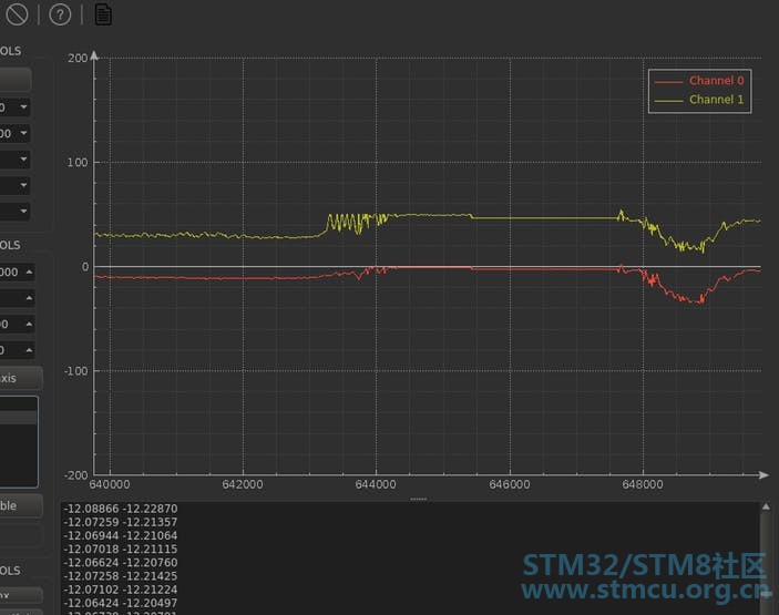
红色:单个IMU,黄色:过滤SuperIMU(滚动) + D8 L% J$ ~: Q! x6 J测量的加速度和陀螺仪速率的加权平均值有助于减少振动环境中的噪声(例如,握手)。然而,成本与获得性能的使用可能不值得结果  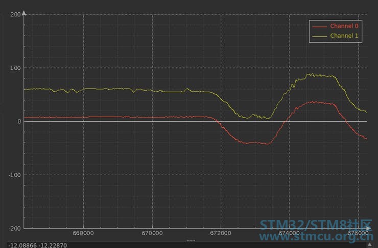
红色:单个IMU,黄色:过滤的SuperIMU ; U. k. |8 V: Y+ n: n& ^) N4 Y* m6 D" r 最后,使用以下命令使用生产编译模式: sudo gprbuild --target=arm-eabi -d superimu.gpr -XLCH=led -XRTS_Profile=ravenscar-full -XLOADER=ROM -XADL_BUILD_CHECKS=Disabled -XADL_BUILD=Production superimu.adb我能够在1ms内达成执行: 
结论 经滤波的SuperIMU允许相对于振动和高加速度计算显着的俯仰和行的稳定值。 使用STM32F746 @200MHz通过过滤13x IMU并在1毫秒内估计一段时间内的音调,取得了良好的效果。 似乎对于火箭的需求,配置12G范围的单个BMI088足以满足火箭需求,而不是为超精确IMU支付300美元,使用两个BMI088突破可能会很有趣,每个25美元。 另一方面,在这个项目中,我学会了如何为STM32制作驱动程序(更新SPI驱动程序,制作UART驱动程序)以及制作BMI088芯片驱动程序。在嵌入式领域中,进行预检查,检查后具有强类型定义的可能性是一个真正的好处。与以前使用的C / C ++相比,在Ada中我不能错过UInt4和UInt8  。 。这是一次有趣的体验,在成功完成项目的这一重大步骤后,我感兴趣的是为我的个人项目挖掘更多并为其他板和传感器制作其他Ada驱动程序。并且还使用Adacore框架继续开发火箭的自动驾驶仪。 0 P: P# X2 X- e% Z; _ t 4 W! T1 y0 |& [. Y7 l. l + Y: A8 M3 t6 p f6 ^% D |
 微信公众号
微信公众号
 手机版
手机版
