|
STM32入门-建立点亮LED的工程 本文通过点亮LED的简单例子,梳理以下如何使用STM32开发工具Keil建立工程。
假设你手里有STM32的开发板。
建立一个存放工程的文件夹,命名为LED。
打开开发工具Keil,Project-New,建立工程。
工程存放位置选择上面创建的文件夹,存储。
根据手上开放板的芯片型号,选择对应的STM32芯片。
提示“复制汇编文件startup_stm32f10x_md.s到项目文件夹,并添加到项目”,选择“是”,这样Keil就帮我们建立了启动文件。
点击New按钮,建立一个文本文件。
输入C语言中的main函数,Ctrl+S保存到LED文件夹下。
工程文件夹上右键,将文件添加到工程中。
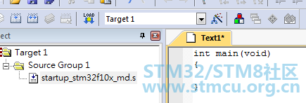
main.c出现在了工程目录中,如下图。
在main.c中添加SystemInit函数。
保存后,编译,程序没有报错,STM32的工程建立完成了。
复制下面的代码,粘贴到SystemInit函数中。
- #define PERIPH_BASE ((unsigned int)0x40000000)
- #define APB2PERIPH_BASE (PERIPH_BASE + 0x10000)
- #define GPIOA_BASE (APB2PERIPH_BASE + 0x0800)
- #define GPIOB_BASE (APB2PERIPH_BASE + 0x0C00)
- #define GPIOC_BASE (APB2PERIPH_BASE + 0x1000)
- #define GPIOD_BASE (APB2PERIPH_BASE + 0x1400)
- #define GPIOE_BASE (APB2PERIPH_BASE + 0x1800)
- #define GPIOF_BASE (APB2PERIPH_BASE + 0x1C00)
- #define GPIOG_BASE (APB2PERIPH_BASE + 0x2000)
- #define GPIOA_ODR_Addr (GPIOA_BASE+12) //0x4001080C
- #define GPIOB_ODR_Addr (GPIOB_BASE+12) //0x40010C0C
- #define GPIOC_ODR_Addr (GPIOC_BASE+12) //0x4001100C
- #define GPIOD_ODR_Addr (GPIOD_BASE+12) //0x4001140C
- #define GPIOE_ODR_Addr (GPIOE_BASE+12) //0x4001180C
- #define GPIOF_ODR_Addr (GPIOF_BASE+12) //0x40011A0C
- #define GPIOG_ODR_Addr (GPIOG_BASE+12) //0x40011E0C
-
- #define BITBAND(addr, bitnum) ((addr & 0xF0000000)+0x2000000+((addr &0xFFFFF)<<5)+(bitnum<<2))
- #define MEM_ADDR(addr) *((volatile unsigned long *)(addr))
-
-
- #define LED0 MEM_ADDR(BITBAND(GPIOA_ODR_Addr,8))
- //#define LED0 *((volatile unsigned long *)(0x422101a0)) //PA8
- typedef struct
- {
- volatile unsigned int CR;
- volatile unsigned int CFGR;
- volatile unsigned int CIR;
- volatile unsigned int APB2RSTR;
- volatile unsigned int APB1RSTR;
- volatile unsigned int AHBENR;
- volatile unsigned int APB2ENR;
- volatile unsigned int APB1ENR;
- volatile unsigned int BDCR;
- volatile unsigned int CSR;
- } RCC_TypeDef;
-
- #define RCC ((RCC_TypeDef *)0x40021000)
-
- typedef struct
- {
- volatile unsigned int CRL;
- volatile unsigned int CRH;
- volatile unsigned int IDR;
- volatile unsigned int ODR;
- volatile unsigned int BSRR;
- volatile unsigned int BRR;
- volatile unsigned int LCKR;
- } GPIO_TypeDef;
-
- #define GPIOA ((GPIO_TypeDef *)GPIOA_BASE)
-
- void LEDInit(void)
- {
- RCC->APB2ENR|=1<<2; //GPIOA 时钟开启
- GPIOA->CRH&=0XFFFFFFF0;
- GPIOA->CRH|=0X00000003;
- }
-
- //粗略延时
- void Delay_ms(volatile unsigned int t)
- {
- unsigned int i,n;
- for(n=0;n<t;n++)
- for(i=0;i<800;i++);
- }
-
- int main(void)
- {
- LEDInit();
- while(1)
- {
- LED0=0;
- Delay_ms(500);
- LED0=1;
- Delay_ms(500);
- }
- }
-
- void SystemInit(void)
- {
-
- }
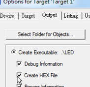
单击魔术棒,点开配置选项。
在“Create HEX File”上打勾。
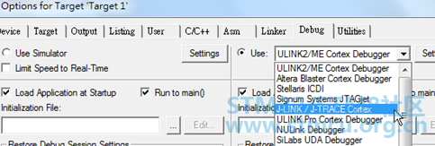
在这里用的是J-Link仿真器。
点击“Build”,如果“0 warnings,0errors”,就可以点击“Load”下载程序到开发板观察效果。
文章出处: STM32嵌入式开发
| 
.png) STMCU小助手
提问时间:2021-3-4 10:04 /
STMCU小助手
提问时间:2021-3-4 10:04 /


 微信公众号
微信公众号
 手机版
手机版
