[Arduino STM32] 01:管脚编号 PIN_MAP- x% J1 x' J9 f* \* a* m
7 L5 D6 j, w( ^0 n4 p$ V
[Arduino STM32] 02:LCD5110 驱动
) X3 Y \3 W! Y+ x
+ U" U% ]; Z+ w* }3 d8 J+ \1 j% x k. @2 ?* R* `+ ]: K
并不是每一个 Arduino AVR 的程序都可以直接使用在 Arduino STM32 板上的,点完了 LCD 之后接下来也要试一下 OLED 的驱动,找了一个使用 Adafruit 库在 Arduino AVR 板上可以运行的例程直接在 STM32 下编译,结果却产生了错误!这貌似是库的支持不兼容,问题目前还在确认中,不过在 Arduino 官网论坛看到了这一篇帖子:. z% ]2 t1 G1 I- Z" F2 ]
/ h! ?/ ~7 `" _8 I5 |1 ghttp://forum.arduino.cc/index.php?topic=265904.21150 Y- W' g% ]. W
1 S+ s% m5 d- p+ v+ H% E有人改写了 Adafruit_SSD1306 库,让这个库可以在 Arduino STM32 底下运行,程序中对于 SPI 接口方式的 OLED 管脚是这么声明的:: B, y' P$ `) D
& o: G3 j9 v# P6 {6 C
#define OLED_DC 22 // D/C 68 k" N$ Y0 k" k" F# `
#define OLED_RST 21 // RST 5# i7 R" |( r. J& j4 Z- [ U
#define OLED_MOSI 20 // SDA 4
' @1 z$ C" X/ M/ K3 h#define OLED_CLK 19 // SCL 3
7 K# E0 m" t# r) U- R#define OLED_CS 14 // --- x Not Connected
; p7 w. _2 u% }6 v% d7 r5 q. k0 J$ C/ G! @" U1 x) |
对应于 Arduino STM32 板的管脚为:- f, P8 V- z0 w$ z( I
4 _3 V. M: o( V! O6 ^5 x# e8 _5 U
22 -> B6; ^& e* Q* I$ o& K/ X" l8 ?( H9 W
21 -> B5
- K# O6 u4 I! |20 -> B4 u0 `" ]4 j( u$ x
19 -> B3
& U% U, m% c% A$ }# D2 h5 u h14 -> A14- t$ U7 G" F1 H" R2 Y' d
0 M4 T+ H7 Y: t3 E主程序:
% D/ N8 L3 S; I& g" B
2 r% `! G. ?) {- j2 c$ i- k) \. i- /*
% F9 P( t" W. O - Using Display: http://www.ebay.com/itm/301504841805
& G+ `; @# i2 V& Q - Compiled Arduino GUI 1.6.1 on 2015-04-01 by M. Ray Burnette& `8 r1 F1 i6 B: S( `' ~# N
- Sketch uses 27,912 bytes (25%) of program storage space. Maximum is 108,000 bytes.
! l+ P" a, c+ C" W - Global variables use 5,616 bytes of dynamic memory.
2 W$ ~! ^, L, i& z" ?4 z - THIS VERSION OF SSD1306 IS SOFTWARE SPI ONLY!!!
6 I t& d" ^6 j( p. \' s# ] - http://github.com/hwiguna/g33k/blob/master/ArduinoProjects/128x64_OLED/HariChord/HariChord.ino 3 \2 u0 ]5 H) c5 g5 K
- */
+ k3 e$ g% n. X - ( Q) m; `4 P+ P& z6 K4 d
- #include ".\Adafruit_GFX.h"
" N6 _: ^5 a! s4 Q. M M. T- P1 |0 w - #include ".\Adafruit_SSD1306.h" N& {" D1 Q. l& j5 m* {: \
9 Q" g$ N% x* f) ]. W+ J- // software SPI works on Maple Mini ARM 32-bit3 O, [; ~5 L( r5 R' E
- // use these settings for the OLED display...
3 ^! o' @% C0 r. Y8 o - // These pin #'s are for Maple Mini/UNO/Nano/Mini328* r& w5 h6 F4 K& V5 g, q! d
- // __Signal__Maple_//__OLED 128x64___$ k% S4 ~+ i) b3 r' Z2 o
- #define OLED_DC 22 // D/C 6! Z) C1 o) p5 i) l
- #define OLED_RST 21 // RST 5+ \* r0 h& B+ W9 I3 }3 ]
- #define OLED_MOSI 20 // SDA 4
; S; W/ {+ T' G- X - #define OLED_CLK 19 // SCL 3
* K& v, w% f+ N4 [% i' g, o - #define OLED_CS 14 // --- x Not Connected) O/ I; }: x( `# J$ ?6 h
- Adafruit_SSD1306 OLED(OLED_MOSI, OLED_CLK, OLED_DC, OLED_RST, OLED_CS);" o' G% ~4 a8 n$ X
0 B; p) L/ P* J2 e8 p4 W t- int nFrames = 36;
# P1 W. j7 V% P - ( ~& C; V% g9 m' W
- void setup() {
; Q: `4 C7 Z: G8 Z0 S9 R - pinMode(17, OUTPUT);+ U; X8 g# b5 A8 i7 F! O' Z
- pinMode(18, OUTPUT);$ q7 v. X" {+ T2 H' C7 h) u
- digitalWrite(17, LOW);9 E7 V) l2 I7 F1 ^
- digitalWrite(18, HIGH);
' [4 `* }7 `5 G3 L) V( P3 o( F - // by default, we'll generate the high voltage from the 3.3v line internally! (neat!)
3 Y8 o) G% o7 u0 C2 ~5 [ - OLED.begin(SSD1306_SWITCHCAPVCC);9 t' Z+ t* {4 z# O( g: ^
- // init done
% g6 r( Y; b7 n/ { - 3 V. e, ?+ D1 D+ L7 M
- // Show image buffer on the display hardware.$ o5 B: Y: R0 f( n, O* b7 _
- // Since the buffer is intialized with an Adafruit splashscreen/ y" I* i. @# d! L9 n& g8 N/ j( N
- // internally, this will display the splashscreen.
; ^/ z1 F. e/ P1 D - // NOTE: You _must_ call display after making any drawing commands7 t7 I% O4 h# Q q Y, f/ ^' o
- // to make them visible on the display hardware!0 B" A& m. z. D& ]
- OLED.display(); // Adafruit Splash
( @+ b, A, T/ c2 t - OLED.clearDisplay(); // Clear the buffer.
5 I: @) K5 O+ Q+ _/ F - // Y = 15 is the Blank Line between yellow / blue8 M% C* B1 [( t o+ k
- }! k$ l! m4 f2 b2 K& ?) ?0 [9 p
( }/ B; g2 n+ x9 e- void loop() {
- N( k- P, d. A - for (int frame=0; frame < nFrames; frame++)! W7 U4 K; T! a$ h0 V" G! N
- {9 p8 P& V+ V9 R5 }
- HariChord(frame);1 D* G4 Z+ U E! {3 {6 J! e# K3 m
- }
! y* ?# [& ^- v" l' l - ( H: `) J% J0 m" ]) p5 T
- for (int frame=(nFrames-1); frame >= 0; frame--)
5 h% g7 ?# l7 V; g' b - { Y5 k- s: w. u
- HariChord(frame);
4 [; P; T9 H- t& o4 @! h - }' c5 A" `+ x* C; G1 y
- }
* K+ J3 B% Q) u3 l& ]: B
: S. T( g4 |* n3 i* G: j- void HariChord(int frame)
% t2 w3 A3 O o* e - {, S. Q: [; A+ f3 E& k5 G
- OLED.clearDisplay();6 f- t; ?/ ]* y
- int n = 7;% b& x9 b5 |2 p
- int r = frame * 64 / nFrames;
, k6 ^, j6 m# d8 B# U - float rot = frame * 2*PI / nFrames;
9 c& _3 I. I, l# y" l" s - for (int i=0; i<(n-1); i++)% N+ c6 `; e. y' n7 X9 P
- {
* s m; E) x7 @+ N2 L7 ^ - float a = rot + i * 2*PI / n;
! F) y% c7 p3 E+ A - int x1 = 64 + cos(a) * r;" r6 _ [# o2 c0 }% D: Z! y. S
- int y1 = 32 + sin(a) * r;- j' e7 c" ~7 f# A/ `! o5 }
- for (int j=i+1; j<n; j++)
% E$ ~! e: P$ j& ?6 o3 N* Z - { J0 B2 }9 h9 H0 v9 D' S+ Z
- a = rot + j * 2*PI / n;3 l8 h0 Q, K x- W0 `
- int x2 = 64 + cos(a) * r;
* f* }( H0 |5 q. F: }% N8 Q - int y2 = 32 + sin(a) * r;
, W: F% ]" _$ Z# p0 z - OLED.drawLine(x1,y1, x2,y2, WHITE);
- Y$ J' _8 `" S8 F! Y9 M. z3 `3 o - }
4 w9 N/ p" T' H - }* r& k) i) }. c0 g( b! {: w6 ?# _
- OLED.display();
# t1 H7 m! w+ r9 q4 O& S9 {! B - }
8 P- U; @6 j) r6 z! B
; k+ D& w0 g5 i0 X运行结果:
" _% Q# R7 f# A4 x# }" L( ?
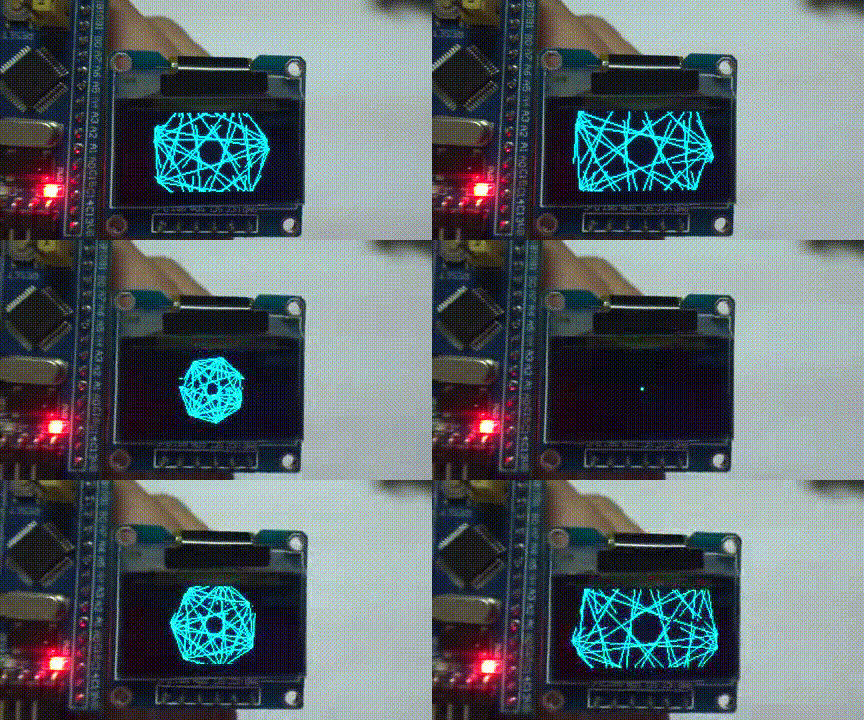
, c+ H8 w; B. R9 Z
: [$ m9 r6 I4 u( t3 t1 ]包括库与例程的压缩文件:
, T8 Q* g8 w% x7 I1 \& u7 o6 Z* ?* n$ J3 |+ v( {$ R' z
 SSD1306-HariChord_swSPI.zip
(15.93 KB, 下载次数: 185) |





 微信公众号
 手机版


我也用的STM32F103,但是在调试SPI OLED屏时,第一次上电有时候没显示,需要复位才可以,搜了一下网上也有人在问,楼主有这种情况么。
我是没碰过,不过依你说的情况我是认为应该是MCU上电开始运行程序的时候 OLED 还没能正常动作,可以尝试MCU上电后延时一小段时间后再来设定 OLED。