.png) STMCU小助手
发布时间:2022-1-18 19:42
STMCU小助手
发布时间:2022-1-18 19:42
|
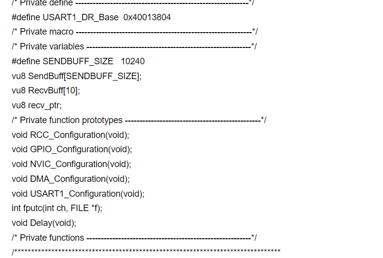
/****************************************************************************** * 本文件实现串口发送功能(通过重构putchar函数,调用printf;或者USART_SendData() * 这里是一个用串口实现大量数据传输的例子,使用了DMA模块进行内存到USART的传输 * 每当USART的发送缓冲区空时,USART模块产生一个DMA事件, * 此时DMA模块响应该事件,自动从预先定义好的发送缓冲区中拿出下一个字节送给USART * 整个过程无需用户程序干预,用户只需启动DMA传输传输即可 * 在仿真器调试时,可以在数据传输过程中暂停运行,此时DMA模块并没有停止 * 串口依然发送,表明DMA传输是一个独立的过程。 * 同时开启接收中断,在串口中断中将数据存入缓冲区,在main主循环中处理 * 作者:jjldc(九九) * 代码硬件基于万利199元的EK-STM32F开发板,CPU=STM32F103VBT6 *******************************************************************************/ /* Includes ------------------------------------------------------------------*/ #include "stm32f10x_lib.h" #include "stdio.h" /* Private typedef -----------------------------------------------------------*/ /* Private define ------------------------------------------------------------*/ #define USART1_DR_Base 0x40013804 /* Private macro -------------------------------------------------------------*/ /* Private variables ---------------------------------------------------------*/ #define SENDBUFF_SIZE 10240 vu8 SendBuff[SENDBUFF_SIZE]; vu8 RecvBuff[10]; vu8 recv_ptr; /* Private function prototypes -----------------------------------------------*/ void RCC_Configuration(void); void GPIO_Configuration(void); void NVIC_Configuration(void); void DMA_Configuration(void); void USART1_Configuration(void); int fputc(int ch, FILE *f); void Delay(void); /* Private functions ---------------------------------------------------------*/ /******************************************************************************* * Function Name : main * Description : Main program. * Input : None * Output : None * Return : None *******************************************************************************/ int main(void) { u16 i; #ifdef DEBUG debug(); #endif recv_ptr = 0; RCC_Configuration(); GPIO_Configuration(); NVIC_Configuration(); DMA_Configuration(); USART1_Configuration(); printf("\r\nSystem Start...\r\n"); printf("Initialling SendBuff... \r\n"); for(i=0;i<SENDBUFF_SIZE;i++) { SendBuff = i&0xff; } printf("Initial success!\r\nWaiting for transmission...\r\n"); //发送去数据已经准备好,按下按键即开始传输 while(GPIO_ReadInputDataBit(GPIOD, GPIO_Pin_3)); printf("Start DMA transmission!\r\n"); //这里是开始DMA传输前的一些准备工作,将USART1模块设置成DMA方式工作 USART_DMACmd(USART1, USART_DMAReq_Tx, ENABLE); //开始一次DMA传输! DMA_Cmd(DMA1_Channel4, ENABLE); //等待DMA传输完成,此时我们来做另外一些事,点灯 //实际应用中,传输数据期间,可以执行另外的任务 while(DMA_GetFlagStatus(DMA1_FLAG_TC4) == RESET) { LED_1_REV; //LED翻转 Delay(); //浪费时间 } //DMA传输结束后,自动关闭了DMA通道,而无需手动关闭 //下面的语句被注释 //DMA_Cmd(DMA1_Channel4, DISABLE); printf("\r\nDMA transmission successful!\r\n"); /* Infinite loop */ while (1) { } } /******************************************************************************* * Function Name : 重定义系统putchar函数int fputc(int ch, FILE *f) * Description : 串口发一个字节 * Input : int ch, FILE *f * Output : * Return : int ch * 这个是使用printf的关键 *******************************************************************************/ int fputc(int ch, FILE *f) { //USART_SendData(USART1, (u8) ch); USART1->DR = (u8) ch; /* Loop until the end of transmission */ while(USART_GetFlagStatus(USART1, USART_FLAG_TXE) == RESET) { } return ch; } /******************************************************************************* * Function Name : Delay * Description : 延时函数 * Input : None * Output : None * Return : None *******************************************************************************/ void Delay(void) { u32 i; for(i=0;i<0xF0000;i++); return; } /******************************************************************************* * Function Name : RCC_Configuration * Description : 系统时钟设置 * Input : None * Output : None * Return : None *******************************************************************************/ void RCC_Configuration(void) { ErrorStatus HSEStartUpStatus; //使能外部晶振 RCC_HSEConfig(RCC_HSE_ON); //等待外部晶振稳定 HSEStartUpStatus = RCC_WaitForHSEStartUp(); //如果外部晶振启动成功,则进行下一步操作 if(HSEStartUpStatus==SUCCESS) { //设置HCLK(AHB时钟)=SYSCLK RCC_HCLKConfig(RCC_SYSCLK_Div1); //PCLK1(APB1) = HCLK/2 RCC_PCLK1Config(RCC_HCLK_Div2); //PCLK2(APB2) = HCLK RCC_PCLK2Config(RCC_HCLK_Div1); //FLASH时序控制 //推荐值:SYSCLK = 0~24MHz Latency=0 // SYSCLK = 24~48MHz Latency=1 // SYSCLK = 48~72MHz Latency=2 FLASH_SetLatency(FLASH_Latency_2); //开启FLASH预取指功能 FLASH_PrefetchBufferCmd(FLASH_PrefetchBuffer_Enable); //PLL设置 SYSCLK/1 * 9 = 8*1*9 = 72MHz RCC_PLLConfig(RCC_PLLSource_HSE_Div1, RCC_PLLMul_9); //启动PLL RCC_PLLCmd(ENABLE); //等待PLL稳定 while(RCC_GetFlagStatus(RCC_FLAG_PLLRDY) == RESET); //系统时钟SYSCLK来自PLL输出 RCC_SYSCLKConfig(RCC_SYSCLKSource_PLLCLK); //切换时钟后等待系统时钟稳定 while(RCC_GetSYSCLKSource()!=0x08); /* //设置系统SYSCLK时钟为HSE输入 RCC_SYSCLKConfig(RCC_SYSCLKSource_HSE); //等待时钟切换成功 while(RCC_GetSYSCLKSource() != 0x04); */ } //下面是给各模块开启时钟 //启动GPIO RCC_APB2PeriphClockCmd(RCC_APB2Periph_GPIOA | RCC_APB2Periph_GPIOB | \ RCC_APB2Periph_GPIOC | RCC_APB2Periph_GPIOD,\ ENABLE); //启动AFIO RCC_APB2PeriphClockCmd(RCC_APB2Periph_AFIO, ENABLE); //启动USART1 RCC_APB2PeriphClockCmd(RCC_APB2Periph_USART1, ENABLE); //启动DMA时钟 RCC_AHBPeriphClockCmd(RCC_AHBPeriph_DMA1, ENABLE); } /******************************************************************************* * Function Name : GPIO_Configuration * Description : GPIO设置 * Input : None * Output : None * Return : None *******************************************************************************/ void GPIO_Configuration(void) { GPIO_InitTypeDef GPIO_InitStructure; //PC口4567脚设置GPIO输出,推挽 2M GPIO_InitStructure.GPIO_Pin = GPIO_Pin_4 | GPIO_Pin_5 | GPIO_Pin_6 | GPIO_Pin_7; GPIO_InitStructure.GPIO_Mode = GPIO_Mode_Out_PP; GPIO_InitStructure.GPIO_Speed = GPIO_Speed_2MHz; GPIO_Init(GPIOC, &GPIO_InitStructure); //KEY2 KEY3 JOYKEY //位于PD口的3 4 11-15脚,使能设置为输入 GPIO_InitStructure.GPIO_Pin = GPIO_Pin_3 | GPIO_Pin_4 | GPIO_Pin_11 | GPIO_Pin_12 |\ GPIO_Pin_13 | GPIO_Pin_14 | GPIO_Pin_15; GPIO_InitStructure.GPIO_Mode = GPIO_Mode_IN_FLOATING; GPIO_Init(GPIOD, &GPIO_InitStructure); //USART1_TX GPIO_InitStructure.GPIO_Pin = GPIO_Pin_9; GPIO_InitStructure.GPIO_Speed = GPIO_Speed_50MHz; GPIO_InitStructure.GPIO_Mode = GPIO_Mode_AF_PP; GPIO_Init(GPIOA, &GPIO_InitStructure); //USART1_RX GPIO_InitStructure.GPIO_Pin = GPIO_Pin_10; GPIO_InitStructure.GPIO_Mode = GPIO_Mode_IN_FLOATING; GPIO_Init(GPIOA, &GPIO_InitStructure); } /******************************************************************************* * Function Name : NVIC_Configuration * Description : NVIC设置 * Input : None * Output : None * Return : None *******************************************************************************/ void NVIC_Configuration(void) { NVIC_InitTypeDef NVIC_InitStructure; #ifdef VECT_TAB_RAM // Set the Vector Table base location at 0x20000000 NVIC_SetVectorTable(NVIC_VectTab_RAM, 0x0); #else /* VECT_TAB_FLASH */ // Set the Vector Table base location at 0x08000000 NVIC_SetVectorTable(NVIC_VectTab_FLASH, 0x0); #endif //设置NVIC优先级分组为Group2:0-3抢占式优先级,0-3的响应式优先级 NVIC_PriorityGroupConfig(NVIC_PriorityGroup_2); //串口接收中断打开 NVIC_InitStructure.NVIC_IRQChannel = USART1_IRQChannel; NVIC_InitStructure.NVIC_IRQChannelPreemptionPriority = 0; NVIC_InitStructure.NVIC_IRQChannelSubPriority = 1; NVIC_InitStructure.NVIC_IRQChannelCmd = ENABLE; NVIC_Init(&NVIC_InitStructure); } /******************************************************************************* * Function Name : USART1_Configuration * Description : NUSART1设置 * Input : None * Output : None * Return : None *******************************************************************************/ void USART1_Configuration(void) { USART_InitTypeDef USART_InitStructure; USART_InitStructure.USART_BaudRate = 9600; USART_InitStructure.USART_WordLength = USART_WordLength_8b; USART_InitStructure.USART_StopBits = USART_StopBits_1; USART_InitStructure.USART_Parity = USART_Parity_No; USART_InitStructure.USART_HardwareFlowControl = USART_HardwareFlowControl_None; USART_InitStructure.USART_Mode = USART_Mode_Tx | USART_Mode_Rx; USART_Init(USART1, &USART_InitStructure); USART_ITConfig(USART1, USART_IT_RXNE, ENABLE); USART_Cmd(USART1, ENABLE); } void DMA_Configuration(void) { DMA_InitTypeDef DMA_InitStructure; //DMA设置: //设置DMA源:内存地址&串口数据寄存器地址 //方向:内存-->外设 //每次传输位:8bit //传输大小DMA_BufferSize=SENDBUFF_SIZE //地址自增模式:外设地址不增,内存地址自增1 //DMA模式:一次传输,非循环 //优先级:中 DMA_DeInit(DMA1_Channel4); DMA_InitStructure.DMA_PeripheralBaseAddr = USART1_DR_Base; DMA_InitStructure.DMA_MemoryBaseAddr = (u32)SendBuff; DMA_InitStructure.DMA_DIR = DMA_DIR_PeripheralDST; DMA_InitStructure.DMA_BufferSize = SENDBUFF_SIZE; DMA_InitStructure.DMA_PeripheralInc = DMA_PeripheralInc_Disable; DMA_InitStructure.DMA_MemoryInc = DMA_MemoryInc_Enable; DMA_InitStructure.DMA_PeripheralDataSize = DMA_PeripheralDataSize_Byte; DMA_InitStructure.DMA_MemoryDataSize = DMA_MemoryDataSize_Byte; DMA_InitStructure.DMA_Mode = DMA_Mode_Normal; DMA_InitStructure.DMA_Priority = DMA_Priority_Medium; DMA_InitStructure.DMA_M2M = DMA_M2M_Disable; DMA_Init(DMA1_Channel4, &DMA_InitStructure); } |
【福利三:逢7发帖赢大礼】4、基于STM32G070板子SPI flash 移植SFUD库
【福利三:逢7发帖赢大礼】基于STM32G070板子的uart shell移植设计
【福利三:逢7发帖赢大礼】3、基于STM32G070板子的YModem串口协议通信
【福利三:逢7发帖赢大礼】2、基于STM32G070板子的OLED移植U8G2库
实战经验 | ClassB功能安全认证代码与应用代码分区的实现要点
STM32G0 系列 I2C 通信异常典型案例分析与解决方案总结
经验分享 | LAT1490 两个STM32G0 I2C 通信异常的案例分析
经验分享 | STM32G0 I2C bootloader Go 命令后调试连接失败:DBG_SWEN 位复位修复
经验分享 | STM32G0B1 待机模式意外唤醒深度解析:RTC 结构体未初始化的隐形坑
经验分享 | STM32G0B1 待机模式意外唤醒深度解析:RTC 结构体未初始化的隐形坑
 微信公众号
微信公众号
 手机版
手机版