STM32F3系列的ADC具有高性能与低功耗的特征,本文以STM30F301C8T6举例。
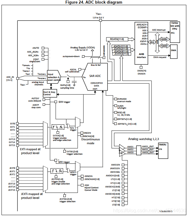
该芯片的ADC具有AHB从总线接口,允许快速数据处理;且ADC转换时间与AHB总线时钟频率无关,相互独立。也就是说,该系列的ADC可以拥有72MHz的时钟频率,12位精度在快速通道下可以达到0.19μs的转换时间,慢速通道也可以达到0.21μs。低精度下(如10位)转换时间仅需0.16μs。并且有自校准以及可编程采样时间等其他STM32系列ADC通有的功能。
时钟
STM32F301x6/8系列具有双时钟域结构,即意味着ADC时钟是从AHB总线独立出来的,所以ADC可以由两个可选择的时钟源输入:
a)ADC时钟可以是一个特定的时钟源,名为“ADCxy_CK(xy=12或34),与AHB时钟独立且异步。它可以配置在RCC中,以提供高达72MHz的频率(PLL输出)。要选择此方案,ADCx_CCR寄存器的位CKMODE[1:0]必须置0。该选项具有ADC时钟频率可以达到最大的优点,无论已选择AHB时钟是什么。ADC时钟最终可除以一下系数进行分频:1、2、4、6、8、12、16、32、64、128、256。
b)ADC时钟可从ADC总线接口的AHB时钟导出,除以一个可编程的系数(1、2或4)。在这种模式下,根据位CKMODE[1:0]可选择一个可编程的除法系数(1、2或4)。要选择此方案,ADCx_CCR寄存器的位CKMODE[1:0]必须与“00”不同。该选项具有绕过时钟域重新同步的优点。当ADC由计时器触发和应用程序要求ADC精确触发且无任何不确定性时非常有用。
电压校准
开始ADC操作前需要进行以下操作:
使能ADC内部电压校准器
启动校准或启用ADC之前,软件必须等待ADC电压调节器的启动时间(TADCVREG_STUB)。这个
时间必须通过软件实现。在最坏的工艺/温度/电源情况下TADCVREG_STUB等于10µs。
转换时间
转换开始和转换结束之间的时间是配置的采样时间加上取决于数据精度的逐次逼近时间分辨率:
外部触发和触发极性
如果EXTEN[1:0]控制位(对于规则转换)或JEXTEN[1:0]位(对于注入转换)与“0b00”不同,则外部事件能够触发所选极性的转换。当软件将位ADSTART置1,规则转换有效;当软件将位JADSTART置1,则注入转换选择有效。
注:外部中断线11触发为事件6—EXT6
代码
adc.h
- #ifndef __ADC_H
- #define __ADC_H
- #include <stm32f30x.h>
- #define ADC1_IN3_PORT GPIOA
- #define ADC1_IN3_PIN GPIO_Pin_2
- void Adc_Init(void);
- #endif
adc.c
- #include "adc.h"
- #include "delay.h"
- void Adc_Init(void)
- {
- /*define structure variables*/
- GPIO_InitTypeDef GPIO_InitStructure;
- ADC_InitTypeDef ADC_InitStructure;
- ADC_CommonInitTypeDef ADC_CommonInitStructure;
- /* Enable ADC1 clock */
- RCC_AHBPeriphClockCmd(RCC_AHBPeriph_GPIOA | RCC_AHBPeriph_ADC12,ENABLE);
- /* Configure the ADC clock */
- /*配置ADC时钟为PLL时钟*/
- RCC_ADCCLKConfig(RCC_ADC12PLLCLK_Div1);
- /*配置GPIO为PA2,Pin3 模拟输入*/
- GPIO_InitStructure.GPIO_Pin = ADC1_IN3_PIN;
- GPIO_InitStructure.GPIO_Mode = GPIO_Mode_AN;
- GPIO_InitStructure.GPIO_PuPd = GPIO_PuPd_NOPULL ;
- GPIO_Init(ADC1_IN3_PORT,&GPIO_InitStructure);
- /*默认初始化ADC结构体*/
- ADC_StructInit(&ADC_InitStructure);
- /* Calibration procedure */
- ADC_VoltageRegulatorCmd(ADC1, ENABLE);
- delay_us(10);
- /*ADC_CalibrationMode_Single: to select the calibration for single channel*/
- ADC_SelectCalibrationMode(ADC1, ADC_CalibrationMode_Single);
- ADC_StartCalibration(ADC1);
- while(ADC_GetCalibrationStatus(ADC1));//waiting finish
- //ADC_CommonInitTypeDef 主要为双重ADC配置,我们只需要配置ADC为独立模式和异步时钟即可
- ADC_CommonInitStructure.ADC_Mode = ADC_Mode_Independent; //独立模式
- ADC_CommonInitStructure.ADC_Clock = ADC_Clock_AsynClkMode; //ADC异步时钟模式
- ADC_CommonInitStructure.ADC_DMAAccessMode = ADC_DMAAccessMode_Disabled;
- ADC_CommonInitStructure.ADC_DMAMode = ADC_DMAMode_OneShot;
- ADC_CommonInitStructure.ADC_TwoSamplingDelay = 0;
- ADC_CommonInit(ADC1, &ADC_CommonInitStructure);
- ADC_InitStructure.ADC_ContinuousConvMode = ADC_ContinuousConvMode_Disable;//连续转换失能
- ADC_InitStructure.ADC_Resolution = ADC_Resolution_12b; //精度为12位
- //外部触发事件6,即EXTI11中断线
- ADC_InitStructure.ADC_ExternalTrigConvEvent = ADC_ExternalTrigConvEvent_6;
- //外部事件上升沿触发,也可选择下降沿,需要与EXTI对应
- ADC_InitStructure.ADC_ExternalTrigEventEdge = ADC_ExternalTrigEventEdge_RisingEdge;
- ADC_InitStructure.ADC_DataAlign = ADC_DataAlign_Right; //数据右对齐
- ADC_InitStructure.ADC_OverrunMode = ADC_OverrunMode_Disable;
- ADC_InitStructure.ADC_AutoInjMode = ADC_AutoInjec_Disable;
- ADC_InitStructure.ADC_NbrOfRegChannel = 1;//the number of ADC channels that will be converted
- ADC_Init(ADC1, &ADC_InitStructure);
- /*配置规则通道参数,设置指定ADC的规则通道,一个序列,采样时间:ADC1通道3,采样时间 1.5个周期*/
- ADC_RegularChannelConfig(ADC1, ADC_Channel_3, 1, ADC_SampleTime_1Cycles5);
- //使能ADC1
- ADC_Cmd(ADC1,ENABLE);
- /* wait for ADRDY */
- while(!ADC_GetFlagStatus(ADC1, ADC_FLAG_RDY));
- }
exti.h
- #ifndef __EXTI_H
- #define __EXTI_H
- #include <stm32f30x.h>
- #define TRIG_PORT GPIOB
- #define TRIG_PIN GPIO_Pin_11
- extern void Exti_Init(void);
- #endif
exti.c
- #include "exti.h"
- void Exti_Init(void)
- {
- /* Private variables ---------------------------------------------------------*/
- EXTI_InitTypeDef EXTI_InitStructure;
- GPIO_InitTypeDef GPIO_InitStructure;
- /* Enable GPIOB clock */
- RCC_AHBPeriphClockCmd(RCC_AHBPeriph_GPIOB, ENABLE);
- /* Enable SYSCFG clock */
- RCC_APB2PeriphClockCmd(RCC_APB2Periph_SYSCFG, ENABLE);
- /* Configure PB11 pin in input no-pull mode */
- GPIO_InitStructure.GPIO_Pin = TRIG_PIN;
- GPIO_InitStructure.GPIO_Mode = GPIO_Mode_IN;
- GPIO_InitStructure.GPIO_PuPd = GPIO_PuPd_NOPULL;
- GPIO_Init(TRIG_PORT, &GPIO_InitStructure);
- /* Connect EXTI11 Line to PB11 pin */
- SYSCFG_EXTILineConfig(EXTI_PortSourceGPIOB, EXTI_PinSource11);
- /* Configure EXTI11 line */
- EXTI_InitStructure.EXTI_Line = EXTI_Line11;
- EXTI_InitStructure.EXTI_Mode = EXTI_Mode_Event;//配置为Event模式即可
- EXTI_InitStructure.EXTI_Trigger = EXTI_Trigger_Rising;//上升沿触发
- EXTI_InitStructure.EXTI_LineCmd = ENABLE;
- EXTI_Init(&EXTI_InitStructure);
- }
注意:即使用外部触发,仍需先将ADSTART位置1方可开启转换,可使用函数ADC_StartConversion设置,时序图如下所示:

之后编写main.c测试即可,可自己一定时间给GPIOx(x=A,B…,本文为GPIOB)11号引脚一个上升沿信号,ADC即会触发相应通道的转换。
main.c
- #include "adc.h"
- #include "exti.h"
- #include "delay.h"
- #include "usart.h"
- int main(void)
- {
- float ADC1ConvertedValue;
- delay_init();
- Exti_Init();
- Adc_Init();
- usart_init();
- ADC_StartConversion(ADC1);//开启ADC1转换
- while(1)
- {
- while(ADC_GetFlagStatus(ADCx, ADC_FLAG_EOC) == RESET);
- /*参考电压为3.3V,12位精度为0xFFF*/
- ADC1ConvertedValue =ADC_GetConversionValue(ADC1)*3.3/0xFFF;
- }
- return 0;
- }
|
.png) STMCU小助手
发布时间:2021-12-5 10:55
STMCU小助手
发布时间:2021-12-5 10:55


 微信公众号
微信公众号
 手机版
手机版