|
下面,我们看看关于NVIC寄存器的描述,都在哪些手册里面有提到 在使用STM32F10x standard peripheral library写有关于stm32中断的程序的时候,需要开启某个特定中断的控制位,除了对应外设的寄存器之外,还需要设置NVIC的相关寄存器的对应位。例如: - /****** STM32 specific Interrupt Numbers *********************************************************/
- WWDG_IRQn = 0, /*!< Window WatchDog Interrupt */
- PVD_IRQn = 1, /*!< PVD through EXTI Line detection Interrupt */
- TAMPER_IRQn = 2, /*!< Tamper Interrupt */
- RTC_IRQn = 3, /*!< RTC global Interrupt */
- FLASH_IRQn = 4, /*!< FLASH global Interrupt */
- RCC_IRQn = 5, /*!< RCC global Interrupt */
- EXTI0_IRQn = 6, /*!< EXTI Line0 Interrupt */
- EXTI1_IRQn = 7, /*!< EXTI Line1 Interrupt */
- EXTI2_IRQn = 8, /*!< EXTI Line2 Interrupt */
- EXTI3_IRQn = 9, /*!< EXTI Line3 Interrupt */
- EXTI4_IRQn = 10, /*!< EXTI Line4 Interrupt */
- DMA1_Channel1_IRQn = 11, /*!< DMA1 Channel 1 global Interrupt */
- DMA1_Channel2_IRQn = 12, /*!< DMA1 Channel 2 global Interrupt */
- DMA1_Channel3_IRQn = 13, /*!< DMA1 Channel 3 global Interrupt */
- DMA1_Channel4_IRQn = 14, /*!< DMA1 Channel 4 global Interrupt */
- DMA1_Channel5_IRQn = 15, /*!< DMA1 Channel 5 global Interrupt */
- DMA1_Channel6_IRQn = 16, /*!< DMA1 Channel 6 global Interrupt */
- DMA1_Channel7_IRQn = 17, /*!< DMA1 Channel 7 global Interrupt */
- NVIC_InitStructure.NVIC_IRQChannel = DMA1_Channel1_IRQn;
- NVIC_InitStructure.NVIC_IRQChannelPreemptionPriority = 0;
- NVIC_InitStructure.NVIC_IRQChannelSubPriority = 0;
- NVIC_InitStructure.NVIC_IRQChannelCmd = ENABLE;
- NVIC_Init(&NVIC_InitStructure);
而NVIC_Init()这个函数: - /**
- * @brief Initializes the NVIC peripheral according to the specified
- * parameters in the NVIC_InitStruct.
- * @param NVIC_InitStruct: pointer to a NVIC_InitTypeDef structure that contains
- * the configuration information for the specified NVIC peripheral.
- * @retval None
- */
- void NVIC_Init(NVIC_InitTypeDef* NVIC_InitStruct)
- {
- uint32_t tmppriority = 0x00, tmppre = 0x00, tmpsub = 0x0F;
-
- /* Check the parameters */
- assert_param(IS_FUNCTIONAL_STATE(NVIC_InitStruct->NVIC_IRQChannelCmd));
- assert_param(IS_NVIC_PREEMPTION_PRIORITY(NVIC_InitStruct->NVIC_IRQChannelPreemptionPriority));
- assert_param(IS_NVIC_SUB_PRIORITY(NVIC_InitStruct->NVIC_IRQChannelSubPriority));
-
- if (NVIC_InitStruct->NVIC_IRQChannelCmd != DISABLE)
- {
- /* Compute the Corresponding IRQ Priority --------------------------------*/
- tmppriority = (0x700 - ((SCB->AIRCR) & (uint32_t)0x700))>> 0x08;
- tmppre = (0x4 - tmppriority);
- tmpsub = tmpsub >> tmppriority;
- tmppriority = (uint32_t)NVIC_InitStruct->NVIC_IRQChannelPreemptionPriority << tmppre;
- tmppriority |= NVIC_InitStruct->NVIC_IRQChannelSubPriority & tmpsub;
- tmppriority = tmppriority << 0x04;
-
- NVIC->IP[NVIC_InitStruct->NVIC_IRQChannel] = tmppriority;
-
- /* Enable the Selected IRQ Channels --------------------------------------*/
- NVIC->ISER[NVIC_InitStruct->NVIC_IRQChannel >> 0x05] =
- (uint32_t)0x01 << (NVIC_InitStruct->NVIC_IRQChannel & (uint8_t)0x1F);
- }
- else
- {
- /* Disable the Selected IRQ Channels -------------------------------------*/
- NVIC->ICER[NVIC_InitStruct->NVIC_IRQChannel >> 0x05] =
- (uint32_t)0x01 << (NVIC_InitStruct->NVIC_IRQChannel & (uint8_t)0x1F);
- }
- }
可以看到,它会去设置几个寄存器:NVIC的IP,ISER,ICER等等,NVIC是基址,为: - #define SCS_BASE (0xE000E000) /*!< System Control Space Base Address */
- #define NVIC_BASE (SCS_BASE + 0x0100) /*!< NVIC Base Address */
- #define SCB_BASE (SCS_BASE + 0x0D00) /*!< System Control Block Base Address */
- #define NVIC ((NVIC_Type *) NVIC_BASE) /*!< NVIC configuration struct */
NVIC_Type为: - /** @addtogroup CMSIS_CM3_NVIC CMSIS CM3 NVIC
- memory mapped structure for Nested Vectored Interrupt Controller (NVIC)
- @{
- */
- typedef struct
- {
- __IO uint32_t ISER[8]; /*!< Offset: 0x000 Interrupt Set Enable Register */
- uint32_t RESERVED0[24];
- __IO uint32_t ICER[8]; /*!< Offset: 0x080 Interrupt Clear Enable Register */
- uint32_t RSERVED1[24];
- __IO uint32_t ISPR[8]; /*!< Offset: 0x100 Interrupt Set Pending Register */
- uint32_t RESERVED2[24];
- __IO uint32_t ICPR[8]; /*!< Offset: 0x180 Interrupt Clear Pending Register */
- uint32_t RESERVED3[24];
- __IO uint32_t IABR[8]; /*!< Offset: 0x200 Interrupt Active bit Register */
- uint32_t RESERVED4[56];
- __IO uint8_t IP[240]; /*!< Offset: 0x300 Interrupt Priority Register (8Bit wide) */
- uint32_t RESERVED5[644];
- __O uint32_t STIR; /*!< Offset: 0xE00 Software Trigger Interrupt Register */
- } NVIC_Type;
- /*@}*/ /* end of group CMSIS_CM3_NVIC */
从上面可以了解到的是,NVIC的寄存器的基址是没有错的,《The Definitive Guide to the ARM Cortex-M3》 85页有个比较详细的内存图;或者查看《Cortex-M3 Technical Reference Manual Revision r1p1》3.4 System address map,6.3 NVIC programmers model:
以及:
B3.4 Nested Vectored Interrupt Controller (NVIC)的相关说明,例如:
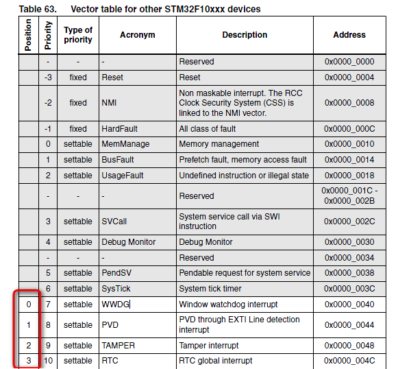
当然,你看权威指南也可以的,在其APPENDIX D:NVIC Registers Quick Reference里面也有所描述。 但还有一个问题,我怎么知道这个Interrupt Set-Enable Registers寄存器的哪个位对应哪个中断呢?例如NVIC_ISER0的第0位对应哪个呢,其实,上面的表B3-31的说明已经说了,每一位对应一个中断号,所以我们还得看看stm32F103对应的中断号,可以查阅《RM0008:Reference manual》的第10章,Interrupts and events中的中断向量表,找到对应MD容量的那个表Table 63. Vector table for other STM32F10xxx devices,前面16个M3内核的中断,不可以从这个寄存器里控制,所以不管,我们从WWDG开始,可以看到这个表中的第一列即对应于寄存器中的某位(超过31的自己换算一下即可):
可以看到,STM32F10x standard peripheral library文件stm32f10x.h中的中断号的定义是能够与这里对应上的。 另外,stm32F103RB的Datasheet(CD00161566)里面的2.3.5 Nested vectored interrupt controller (NVIC)提到F103仅有43个可屏蔽中断,所以只需用到NVIC_ISER0和NVIC_ISER1来设置启用外设中断。
| .png) STMCU小助手
发布时间:2022-1-17 22:09
STMCU小助手
发布时间:2022-1-17 22:09


 微信公众号
微信公众号
 手机版
手机版