


.png) STMCU小助手
发布时间:2022-1-29 01:01
STMCU小助手
发布时间:2022-1-29 01:01
|
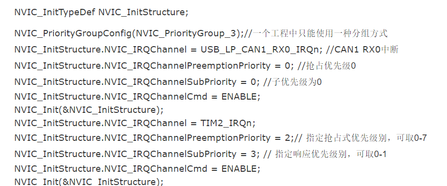
在stm32中是要配置nvic的。何为nvic,对于我这样的初学者来说,直观感受就是在设置为中断后 还需要配置 中断的优先级nvic就是搞这个的、 那么具体的需要配置些什么那? void NVIC_Configuration(void) { NVIC_PriorityGroupConfig(NVIC_PriorityGroup_2); //设置NVIC中断分组2:2位抢占优先级,2位响应优先级 } NVIC_InitStructure.NVIC_IRQChannel = EXTI0_IRQn; //使能按键WK_UP所在的外部中断通道 NVIC_InitStructure.NVIC_IRQChannelPreemptionPriority = 0x02; //抢占优先级2, NVIC_InitStructure.NVIC_IRQChannelSubPriority = 0x03; //子优先级3 NVIC_InitStructure.NVIC_IRQChannelCmd = ENABLE; //使能外部中断通道 NVIC_Init(&NVIC_InitStructure); NVIC_InitStructure.NVIC_IRQChannel // 通道在头文件中 stm32f10x的定义- H v O! @9 s/ |, X ?+ }2 n* l 2 [8 C# u8 x7 N( \' @ typedef enum IRQn { /****** Cortex-M3 Processor Exceptions Numbers ***************************************************/ NonMaskableInt_IRQn = -14, /*!< 2 Non Maskable Interrupt */ MemoryManagement_IRQn = -12, /*!< 4 Cortex-M3 Memory Management Interrupt *// I- i6 H' {# E# |; r7 _; E% p BusFault_IRQn = -11, /*!< 5 Cortex-M3 Bus Fault Interrupt */& a; O9 f8 ~4 w, y/ f$ L- ^' R- E UsageFault_IRQn = -10, /*!< 6 Cortex-M3 Usage Fault Interrupt */ SVCall_IRQn = -5, /*!< 11 Cortex-M3 SV Call Interrupt */' q1 `$ [* r( a: S& B8 O DebugMonitor_IRQn = -4, /*!< 12 Cortex-M3 Debug Monitor Interrupt */ PendSV_IRQn = -2, /*!< 14 Cortex-M3 Pend SV Interrupt */ SysTick_IRQn = -1, /*!< 15 Cortex-M3 System Tick Interrupt */ /****** STM32 specific Interrupt Numbers *********************************************************/ WWDG_IRQn = 0, /*!< Window WatchDog Interrupt */ PVD_IRQn = 1, /*!< PVD through EXTI Line detection Interrupt */) k. W0 [& I, [" x$ U. b3 c0 { TAMPER_IRQn = 2, /*!< Tamper Interrupt */ f# k0 B) e/ c3 w! h: Y+ p8 A RTC_IRQn = 3, /*!< RTC global Interrupt */ FLASH_IRQn = 4, /*!< FLASH global Interrupt */( ~# _0 U* D8 z( J {! _: H9 S6 ] RCC_IRQn = 5, /*!< RCC global Interrupt */ g% U3 b7 G: S7 i: l" A EXTI0_IRQn = 6, /*!< EXTI Line0 Interrupt */5 X1 J- [; }! H2 t( s EXTI1_IRQn = 7, /*!< EXTI Line1 Interrupt */0 \- ~% h) t9 C$ A0 L/ C EXTI2_IRQn = 8, /*!< EXTI Line2 Interrupt */ EXTI3_IRQn = 9, /*!< EXTI Line3 Interrupt */; ]8 f+ D' e. U- w1 D6 V* B' M; o0 A6 ?8 k EXTI4_IRQn = 10, /*!< EXTI Line4 Interrupt */5 z ]7 k7 a. d: v9 U3 n DMA1_Channel1_IRQn = 11, /*!< DMA1 Channel 1 global Interrupt */ DMA1_Channel2_IRQn = 12, /*!< DMA1 Channel 2 global Interrupt */ DMA1_Channel3_IRQn = 13, /*!< DMA1 Channel 3 global Interrupt */ DMA1_Channel4_IRQn = 14, /*!< DMA1 Channel 4 global Interrupt */7 Y8 u1 s& l: ? M8 ]8 ?* m1 ] DMA1_Channel5_IRQn = 15, /*!< DMA1 Channel 5 global Interrupt */$ V- A6 g9 p; F0 q! }0 b DMA1_Channel6_IRQn = 16, /*!< DMA1 Channel 6 global Interrupt */ DMA1_Channel7_IRQn = 17, /*!< DMA1 Channel 7 global Interrupt */- Z. ]' j; O4 X% ? #ifdef STM32F10X_LD) J* O+ c4 j" R8 c ADC1_2_IRQn = 18, /*!< ADC1 and ADC2 global Interrupt */: A/ b* G) K6 r/ U$ H/ _ USB_HP_CAN1_TX_IRQn = 19, /*!< USB Device High Priority or CAN1 TX Interrupts */ USB_LP_CAN1_RX0_IRQn = 20, /*!< USB Device Low Priority or CAN1 RX0 Interrupts */: R! U y3 P! K CAN1_RX1_IRQn = 21, /*!< CAN1 RX1 Interrupt */ CAN1_SCE_IRQn = 22, /*!< CAN1 SCE Interrupt */ EXTI9_5_IRQn = 23, /*!< External Line[9:5] Interrupts */ TIM1_BRK_IRQn = 24, /*!< TIM1 Break Interrupt */0 y9 ^) p6 [9 E# ]2 V0 ~ TIM1_UP_IRQn = 25, /*!< TIM1 Update Interrupt */ TIM1_TRG_COM_IRQn = 26, /*!< TIM1 Trigger and Commutation Interrupt */- d4 Q/ g2 X, f8 h, _7 X' s TIM1_CC_IRQn = 27, /*!< TIM1 Capture Compare Interrupt */6 a! J/ q; ~9 d Q) |5 A$ u- i- O7 e TIM2_IRQn = 28, /*!< TIM2 global Interrupt */( D* H T3 b$ S TIM3_IRQn = 29, /*!< TIM3 global Interrupt */- e1 A" y B6 A) p I2C1_EV_IRQn = 31, /*!< I2C1 Event Interrupt *// G+ i5 l2 p1 y- E: W I2C1_ER_IRQn = 32, /*!< I2C1 Error Interrupt */ SPI1_IRQn = 35, /*!< SPI1 global Interrupt */5 b+ p& y8 P, _% g$ X8 f USART1_IRQn = 37, /*!< USART1 global Interrupt */ USART2_IRQn = 38, /*!< USART2 global Interrupt */ EXTI15_10_IRQn = 40, /*!< External Line[15:10] Interrupts */ RTCAlarm_IRQn = 41, /*!< RTC Alarm through EXTI Line Interrupt */ USBWakeUp_IRQn = 42 /*!< USB Device WakeUp from suspend through EXTI Line Interrupt */ + M6 ~3 W. n: A$ o% O* \: O" \ #endif /* STM32F10X_LD */ ' q5 h, [5 _ ]- z- O+ F* | t0 N ^ STM32有43个channel的settable的中断源;AIRC(Application Interrupt and Reset Register)寄存器中有用于指定优先级的4 bits。这4个bits用于分配preemption优先级和sub优先级,在STM32的固件库中定义如下 #define NVIC_PriorityGroup_0 ((u32)0x700)$ M0 J& a0 r0 n& P' f #define NVIC_PriorityGroup_1 ((u32)0x600)* U7 ]. I; k4 n #define NVIC_PriorityGroup_2 ((u32)0x500)8 Y+ n; i3 J5 N7 _0 n( h #define NVIC_PriorityGroup_3 ((u32)0x400)5 k* B' C }7 d! x, d #define NVIC_PriorityGroup_4 ((u32)0x300) 每个工程只能有一种分组方式: 按NVIC_PriorityGroup_0来分组:抢占优先级为1个,子优先级为16个; 按NVIC_PriorityGroup_1来分组:抢占优先级为2个,子优先级为8个; 按NVIC_PriorityGroup_2来分组:抢占优先级为4个,子优先级为4个; 按NVIC_PriorityGroup_3来分组:抢占优先级为8个,子优先级为2个; 按NVIC_PriorityGroup_0来分组:抢占优先级为16个,子优先级为1个; 抢占优先级高的中断可以打断抢占优先级低的中断;抢占优先级相同时比较响应优先级(子优先级)。 先设定分组方式 例:NVIC_PriorityGroupConfig(NVIC_PriorityGroup_4); //按NVIC_PriorityGroup_4来分组 此时,有一中断EXTI0_IRQChannel,你指定他为抢占优先级8,则 NVIC_InitStructure.NVIC_IRQChannel = EXTI0_IRQChannel; NVIC_InitStructure.NVIC_IRQChannelPreemptionPriority = 8; // 指定抢占式优先级别,可取0-15 又有1中断SPI1_IRQChannel,设定如下 NVIC_InitStructure.NVIC_IRQChannel = SPI1_IRQChannel;0 [+ X& h7 O+ S2 w NVIC_InitStructure.NVIC_IRQChannelPreemptionPriority = 0; // 指定抢占式优先级别,可取0-15 则SPI1_IRQChannel的抢占优先级高,EXTI0_IRQChannel做事的时候可以打断(嵌套) " ?4 y5 ~. ]5 s( P: ~又:若分组方式为:NVIC_PriorityGroupConfig(NVIC_PriorityGroup_3); //按NVIC_PriorityGroup_3来分组 此时就有8个抢占优先级,2个子优先级; EXTI0_IRQChannel中断,你指定他为抢占优先级3,则:( f" e3 C* x$ Y% { M NVIC_InitStructure.NVIC_IRQChannel = EXTI0_IRQChannel;$ L6 c9 _0 c0 p. r NVIC_InitStructure.NVIC_IRQChannelPreemptionPriority = 2; // 指定抢占式优先级别,可取0-7 还需要指定他的阶层:9 N( p# u6 q0 X# ^ NVIC_InitStructure.NVIC_IRQChannelSubPriority = 0; // 指定响应优先级别,可取0-1 又有TIM2_IRQn中断,设定如下: NVIC_InitStructure.NVIC_IRQChannel = TIM2_IRQn; 1 x. j! L9 Z. D+ s+ c9 ? NVIC_InitStructure.NVIC_IRQChannelPreemptionPriority = 2;// 指定抢占式优先级别,可取0-7 NVIC_InitStructure.NVIC_IRQChannelSubPriority = 3; // 指定响应优先级别,可取0-1 由于抢占优先级相同,响应优先级EXTI0_IRQChannel中断高于TIM2_IRQn中断,所以EXTI0_IRQChannel可以打断TIM2_IRQn; 还有一USB_LP_CAN1_RX0_IRQn,设定如下: NVIC_InitStructure.NVIC_IRQChannel = USB_LP_CAN1_RX0_IRQn; //CAN1 RX0中断 NVIC_InitStructure.NVIC_IRQChannelPreemptionPriority = 0; //抢占优先级0 NVIC_InitStructure.NVIC_IRQChannelSubPriority = 0; //响应优先级别0,可取0-1 USB_LP_CAN1_RX0_IRQn优先级最高,前两中断发生时,它都可以打断。 附: void NVIC_Config(void) { NVIC_InitTypeDef NVIC_InitStructure; NVIC_PriorityGroupConfig(NVIC_PriorityGroup_3);//一个工程中只能使用一种分组方式 NVIC_InitStructure.NVIC_IRQChannel = USB_LP_CAN1_RX0_IRQn; //CAN1 RX0中断1 M8 g% r+ _9 W; a7 o* v* f NVIC_InitStructure.NVIC_IRQChannelPreemptionPriority = 0; //抢占优先级01 a7 A+ _: B6 C, b NVIC_InitStructure.NVIC_IRQChannelSubPriority = 0; //子优先级为0 NVIC_InitStructure.NVIC_IRQChannelCmd = ENABLE; NVIC_Init(&NVIC_InitStructure);( j! u4 X" n5 k8 H- R- D NVIC_InitStructure.NVIC_IRQChannel = TIM2_IRQn;7 e; @( Y1 l% P% B NVIC_InitStructure.NVIC_IRQChannelPreemptionPriority = 2;// 指定抢占式优先级别,可取0-79 ^" o5 n2 k4 f6 s" T( i' D NVIC_InitStructure.NVIC_IRQChannelSubPriority = 3; // 指定响应优先级别,可取0-10 K" n1 M: p G0 j0 [, Z; O NVIC_InitStructure.NVIC_IRQChannelCmd = ENABLE; NVIC_Init(&NVIC_InitStructure);# w; M. I. W0 Z6 O1 d NVIC_InitStructure.NVIC_IRQChannel = EXTI0_IRQChannel;: t# Y9 n) h0 V0 E& L* c9 ~ NVIC_InitStructure.NVIC_IRQChannelPreemptionPriority = 2; // 指定抢占式优先级别,可取0-77 ?- W4 u8 C( J I6 \6 K NVIC_InitStructure.NVIC_IRQChannelSubPriority = 0; // 指定响应优先级别,可取0-1 NVIC_InitStructure.NVIC_IRQChannelCmd = ENABLE;! _) g) c, @; T0 p NVIC_Init(&NVIC_InitStructure); } 6 M: l' Y# g/ M. ~2 _# D5 O |
实战经验 | 基于STM32G0B1的全桥移相+同步整流PWM解决方案
DMA 原理从 0 到 1:为什么它能解放 CPU?一文讲透 DMA 的工作流程
【福利三:逢7发帖赢大礼】8、基于STM32G070板子的Ymodem串口协议IAP Bootloader开发
【福利三:逢7发帖赢大礼】7、基于STM32G070板子TF卡的FATFS移植
【福利三:逢7发帖赢大礼】6、基于STM32G070板子spiflash的FATFS移植
【福利三:逢7发帖赢大礼】5、基于STM32G070板子IRDA红外遥控接收解码
【福利三:逢7发帖赢大礼】4、基于STM32G070板子SPI flash 移植SFUD库
【福利三:逢7发帖赢大礼】基于STM32G070板子的uart shell移植设计
【福利三:逢7发帖赢大礼】3、基于STM32G070板子的YModem串口协议通信
【福利三:逢7发帖赢大礼】2、基于STM32G070板子的OLED移植U8G2库
 微信公众号
微信公众号
 手机版
手机版