问题:
该问题由某客户提出,发生在 STM32F401CEY6 401CEY6 401CEY6 器件上。据其工程师讲述:在程序中,在进入 STOP 模式之前他已经将 STM32F401 的 I/O 口做完处理了,但是电流仍然比数据手册写的数值还要大很多,不知道是在哪里消耗了电流。希望能帮他验证一下。
调研:
我们先来看一下 STM32F401 的数据手册中,对其在 STOP 模式下工作的电流的参数:

按客户的要求,我们主要是验证在 STOP 模式下,调压器在低功耗模式下的电流,也就是表格中典型电流为 42uA 的那个值。
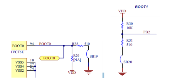
我们使用 STM32F401 的 Discovery 板进行验证,因为在 Discovery 板上只需要把 Idd 的那个 JP2 的跳线帽拿掉接上电流表就可以测试电流了,当然,我们必须要检查一下,这个电流供进来给 MCU 作为VDD 时,还可能连接什么电路会导致电流消耗的,检查了一遍,主要是要注意 BOOT0 以及 BOOT1脚。
IU6}S`I{1BSRZ_$()UI.png")
由于运行用户代码,所以 BOOT0 和 BOOT1 都将接到低电平上,所以电路上要确保 SB19 和 SB20 短路,但是我们可以看到,BOOT1 上面从 VDD 到 R30 到 R31 再到 GND,将会有一个电流产生,所以必须要把 R30 取下来。BOOT0 由于本身 R29 就没有接,所以倒是没有关系。
好,那现在开始验证电流,我们使用 32F401CDISCOVERY 的固件库中的 PWR_STOP 的例程来验证。因为不使用 RTC,所以我们将程序中的 RTC 部分删掉:将 stm32f4xx_it.c 中的 voidRTC_WKUP_IRQHandler(void)函数中的内容删除,再将 main.c 中的 static void RTC_Config(void)函数删除,在 int main(void)主函数中也清除掉相关的内容,主函数如下:
- int main(void)
- {
- /*!< At this stage the microcontroller clock setting is already configured,
- this is done through SystemInit() function which is called from startup
- file (startup_stm32f401xx.s) before to branch to application main.
- To reconfigure the default setting of SystemInit() function, refer to
- system_stm32f4xx.c file
- */
- /* Configure the SysTick to generate an interrupt each 250 ms */
- SysTick_Configuration();
- /* Initialize LEDs and User Button mounted on STM32F401C-DISCO board */
- STM_EVAL_LEDInit(LED3);
- STM_EVAL_LEDInit(LED6);
- /* Key button (EXTI_Line0) will be used to wakeup ths system from STOP mode */
- STM_EVAL_PBInit(BUTTON_USER, BUTTON_MODE_EXTI);
- while (1)
- {
- /* Insert 5 second delay */
- Delay(20);
- /* Turn OFF LED3 */
- STM_EVAL_LEDOff(LED3);
- /* Enter Stop Mode */
- PWR_EnterSTOPMode(PWR_Regulator_LowPower, PWR_STOPEntry_WFI);
- /* Configures system clock after wake-up from STOP: enable HSE, PLL and select
- PLL as system clock source (HSE and PLL are disabled in STOP mode) */
- SYSCLKConfig_STOP();
- }
- }
编译,下载测试电流,进入 STOP 模式后电流为 2.23mA 左右。
大家应该已经发现,此例程在进入 STOP 模式之前,并没有对 I/O 口进行处理,导致很多配置为输入浮空的 I/O 口在受到外界干扰的时候,状态不定,消耗了大量的电流。在实际应用中,在进入 STOP模式前,可以根据实际情况,将 I/O 口设置成模拟输入,输入+上下拉电阻,或者输出固定电平。所以,在这里,我们将我们没用到的 I/O 通通设置为模拟输入,只保留 PA0 作为按键,产生外部中断来将 MCU 从 STOP 模式中唤醒。配置 I/O 口后,为了方便从 STOP 模式唤醒后还能直观地看到 LED灯,我们需要在 stm32f4xx_it.c 的 void EXTI0_IRQHandler(void)函数中加入 LED6 的初始化函数STM_EVAL_LEDInit(LED6),在 main()主函数的 SYSCLKConfig_STOP()之后加上STM_EVAL_LEDInit(LED3)。
void EXTI0_IRQHandler(void)如下:
- void EXTI0_IRQHandler(void)
- {
- if(EXTI_GetITStatus(USER_BUTTON_EXTI_LINE) != RESET)
- {
- /* Clear the USER Button EXTI line pending bit */
- EXTI_ClearITPendingBit(USER_BUTTON_EXTI_LINE);
- /* Toggle LED6 */
- STM_EVAL_LEDInit(LED6);
- STM_EVAL_LEDToggle(LED6);
- }
- }
Int main(void)中的主循环 while(1)中的内容如下:
- while (1)
- {
- /* Insert 5 second delay */
- Delay(20);
- /* Turn OFF LED3 */
- STM_EVAL_LEDOff(LED3);
- /* Configure all I/O ports */
- GPIO_InitTypeDef GPIO_InitStructure;
- RCC_AHB1PeriphClockCmd(RCC_AHB1Periph_GPIOA, ENABLE);
- RCC_AHB1PeriphClockCmd(RCC_AHB1Periph_GPIOB, ENABLE);
- RCC_AHB1PeriphClockCmd(RCC_AHB1Periph_GPIOC, ENABLE);
- RCC_AHB1PeriphClockCmd(RCC_AHB1Periph_GPIOD, ENABLE);
- RCC_AHB1PeriphClockCmd(RCC_AHB1Periph_GPIOE, ENABLE);
- GPIO_InitStructure.GPIO_Pin = GPIO_Pin_All;
- GPIO_InitStructure.GPIO_Mode = GPIO_Mode_AN;
- GPIO_InitStructure.GPIO_OType = GPIO_OType_PP;
- GPIO_InitStructure.GPIO_PuPd = GPIO_PuPd_NOPULL;
- GPIO_InitStructure.GPIO_Speed = GPIO_Speed_2MHz;
- GPIO_Init(GPIOB, &GPIO_InitStructure);
- GPIO_Init(GPIOC, &GPIO_InitStructure);
- GPIO_Init(GPIOD, &GPIO_InitStructure);
- GPIO_Init(GPIOE, &GPIO_InitStructure);
- GPIO_InitStructure.GPIO_Pin = (~GPIO_Pin_0);
- GPIO_Init(GPIOA, &GPIO_InitStructure);
- /* Enter Stop Mode */
- PWR_EnterSTOPMode(PWR_Regulator_LowPower, PWR_STOPEntry_WFI);
- /* Configures system clock after wake-up from STOP: enable HSE, PLL and select
- PLL as system clock source (HSE and PLL are disabled in STOP mode) */
- SYSCLKConfig_STOP();
- STM_EVAL_LEDInit(LED3);
- }
编译,下载测试电流,进入 STOP 模式后电流为 155uA 左右。这不对啊,距离我们看到的 42uA 还有很大的差距。客户就是在这里不知道为什么了。
我们来继续查找原因,客户跟 32F401CDISCOVERY 板一样,使用了外部 8MHz 晶振,所以当使用HSE 的时候,PH0/PH1 被作为 OSC_IN 和 OSC_OUT。问题来了,当进入 STOP 模式时,HSE RC振荡器被禁止,PH0/PH1 这个时候就不再是 OSC_IN 和 OSC_OUT 了,变成普通的 I/O 口,而且是处理浮空输入状态。所以我们还得需要对这两个引脚的 I/O 配置进行处理。再来修改 main()主函数中的while(1)主循环,加入对 PH0/PH1 的处理,程序如下:
- while (1)
- {
- /* Insert 5 second delay */
- Delay(20);
- /* Turn OFF LED3 */
- STM_EVAL_LEDOff(LED3);
- /* Configure all I/O ports */
- GPIO_InitTypeDef GPIO_InitStructure;
- RCC_AHB1PeriphClockCmd(RCC_AHB1Periph_GPIOA, ENABLE);
- RCC_AHB1PeriphClockCmd(RCC_AHB1Periph_GPIOB, ENABLE);
- RCC_AHB1PeriphClockCmd(RCC_AHB1Periph_GPIOC, ENABLE);
- RCC_AHB1PeriphClockCmd(RCC_AHB1Periph_GPIOD, ENABLE);
- RCC_AHB1PeriphClockCmd(RCC_AHB1Periph_GPIOE, ENABLE);
- RCC_AHB1PeriphClockCmd(RCC_AHB1Periph_GPIOH, ENABLE);
- GPIO_InitStructure.GPIO_Pin = GPIO_Pin_All;
- GPIO_InitStructure.GPIO_Mode = GPIO_Mode_AN;
- GPIO_InitStructure.GPIO_OType = GPIO_OType_PP;
- GPIO_InitStructure.GPIO_PuPd = GPIO_PuPd_NOPULL;
- GPIO_InitStructure.GPIO_Speed = GPIO_Speed_2MHz;
- GPIO_Init(GPIOB, &GPIO_InitStructure);
- GPIO_Init(GPIOC, &GPIO_InitStructure);
- GPIO_Init(GPIOD, &GPIO_InitStructure);
- GPIO_Init(GPIOE, &GPIO_InitStructure);
- GPIO_Init(GPIOH, &GPIO_InitStructure);
- GPIO_InitStructure.GPIO_Pin = (~GPIO_Pin_0);
- GPIO_Init(GPIOA, &GPIO_InitStructure);
- /* Enter Stop Mode */
- PWR_EnterSTOPMode(PWR_Regulator_LowPower, PWR_STOPEntry_WFI);
- /* Configures system clock after wake-up from STOP: enable HSE, PLL and select
- PLL as system clock source (HSE and PLL are disabled in STOP mode) */
- SYSCLKConfig_STOP();
- STM_EVAL_LEDInit(LED3);
- }
编译,下载测试电流,进入 STOP 模式后电流为 38.5uA。已经比我们从表格中看到 42uA 还小了,任务完成。当然,数据手册中 42uA 是在 VDD=3.3V 的情况下数值,而我们的 Discovery 板的 VDD 为3V。
我们还可以再测一下让 Flash 进入掉电模式下的电流,修改 while(1)程序如下:
- while (1)
- {
- /* Insert 5 second delay */
- Delay(20);
- /* Turn OFF LED3 */
- STM_EVAL_LEDOff(LED3);
- /* Configure all I/O ports */
- GPIO_InitTypeDef GPIO_InitStructure;
- RCC_AHB1PeriphClockCmd(RCC_AHB1Periph_GPIOA, ENABLE);
- RCC_AHB1PeriphClockCmd(RCC_AHB1Periph_GPIOB, ENABLE);
- RCC_AHB1PeriphClockCmd(RCC_AHB1Periph_GPIOC, ENABLE);
- RCC_AHB1PeriphClockCmd(RCC_AHB1Periph_GPIOD, ENABLE);
- RCC_AHB1PeriphClockCmd(RCC_AHB1Periph_GPIOE, ENABLE);
- RCC_AHB1PeriphClockCmd(RCC_AHB1Periph_GPIOH, ENABLE);
- GPIO_InitStructure.GPIO_Pin = GPIO_Pin_All;
- GPIO_InitStructure.GPIO_Mode = GPIO_Mode_AN;
- GPIO_InitStructure.GPIO_OType = GPIO_OType_PP;
- GPIO_InitStructure.GPIO_PuPd = GPIO_PuPd_NOPULL;
- GPIO_InitStructure.GPIO_Speed = GPIO_Speed_2MHz;
- GPIO_Init(GPIOB, &GPIO_InitStructure);
- GPIO_Init(GPIOC, &GPIO_InitStructure);
- GPIO_Init(GPIOD, &GPIO_InitStructure);
- GPIO_Init(GPIOE, &GPIO_InitStructure);
- GPIO_Init(GPIOH, &GPIO_InitStructure);
- GPIO_InitStructure.GPIO_Pin = (~GPIO_Pin_0);
- GPIO_Init(GPIOA, &GPIO_InitStructure);
- /* Configure flash power down mode */
- PWR_FlashPowerDownCmd(ENABLE);
- /* Enter Stop Mode */
- PWR_EnterSTOPMode(PWR_Regulator_LowPower, PWR_STOPEntry_WFI);
- /* Configures system clock after wake-up from STOP: enable HSE, PLL and select
- PLL as system clock source (HSE and PLL are disabled in STOP mode) */
- SYSCLKConfig_STOP();
- STM_EVAL_LEDInit(LED3);
- }
编译,下载测试电流,进入 STOP 模式后电流为 10.2uA,与数据手册中的典型值基本一致。
结论:
客户在硬件上使用了 HSE,而在进入 STOP 模式前,只对其他 I/O 进行了处理,漏掉了 HSE 对应的两个I/O 口,导致电流过大。
处理:
对 PH0/PH1 进行处理,进入 STOP 模式前配置成模拟输入。
建议:
在进入 STOP 模式之前,一定要根据实际电路情况,细致地对各个 I/O 口进行处理。
|
.png) STMCU小助手
发布时间:2022-3-5 09:44
STMCU小助手
发布时间:2022-3-5 09:44
 微信公众号
微信公众号
 手机版
手机版