一、串口初始化过程
1、时钟使能;
2、GPIO初始化;
3、串口波特率设置;
4、串口控制;
5、数据发送与接收
二、几个重要的串口函数
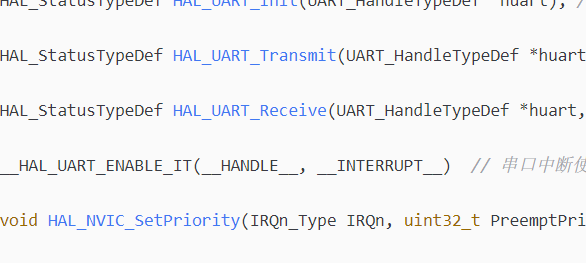
- HAL_StatusTypeDef HAL_UART_Init(UART_HandleTypeDef *huart); // 串口初始化
- HAL_StatusTypeDef HAL_UART_Transmit(UART_HandleTypeDef *huart, uint8_t *pData, uint16_t Size, uint32_t Timeout); // 串口发送
- HAL_StatusTypeDef HAL_UART_Receive(UART_HandleTypeDef *huart, uint8_t *pData, uint16_t Size, uint32_t Timeout); // 串口接收
- __HAL_UART_ENABLE_IT(__HANDLE__, __INTERRUPT__) // 串口中断使能
- void HAL_NVIC_SetPriority(IRQn_Type IRQn, uint32_t PreemptPriority, uint32_t SubPriority); // 设置中断优先级
- void HAL_NVIC_EnableIRQ(IRQn_Type IRQn); // 使能中断
三、几个重要的结构
- // 串口初始化结构体 包含了串口句柄 波特率配置 发送接收缓存 dma等
- // 我们只描述前两个基本功能,对效率要求极高可以使用DMA。
- typedef struct
- {
- USART_TypeDef *Instance; /*!< UART registers base address */
- UART_InitTypeDef Init; /*!< UART communication parameters */
- UART_AdvFeatureInitTypeDef AdvancedInit; /*!< UART Advanced Features initialization parameters */
- uint8_t *pTxBuffPtr; /*!< Pointer to UART Tx transfer Buffer */
- uint16_t TxXferSize; /*!< UART Tx Transfer size */
- uint16_t TxXferCount; /*!< UART Tx Transfer Counter */
- uint8_t *pRxBuffPtr; /*!< Pointer to UART Rx transfer Buffer */
- uint16_t RxXferSize; /*!< UART Rx Transfer size */
- uint16_t RxXferCount; /*!< UART Rx Transfer Counter */
- uint16_t Mask; /*!< UART Rx RDR register mask */
- DMA_HandleTypeDef *hdmatx; /*!< UART Tx DMA Handle parameters */
- DMA_HandleTypeDef *hdmarx; /*!< UART Rx DMA Handle parameters */
- HAL_LockTypeDef Lock; /*!< Locking object */
- __IO HAL_UART_StateTypeDef gState; /*!< UART state information related to global Handle management
- and also related to Tx operations.
- This parameter can be a value of @ref HAL_UART_StateTypeDef */
- __IO HAL_UART_StateTypeDef RxState; /*!< UART state information related to Rx operations.
- This parameter can be a value of @ref HAL_UART_StateTypeDef */
- __IO uint32_t ErrorCode; /*!< UART Error code */
- }UART_HandleTypeDef;
- // 串口的操作句柄 如 USART1 USART2 USART3等
- typedef struct
- {
- __IO uint32_t CR1; /*!< USART Control register 1, Address offset: 0x00 */
- __IO uint32_t CR2; /*!< USART Control register 2, Address offset: 0x04 */
- __IO uint32_t CR3; /*!< USART Control register 3, Address offset: 0x08 */
- __IO uint32_t BRR; /*!< USART Baud rate register, Address offset: 0x0C */
- __IO uint32_t GTPR; /*!< USART Guard time and prescaler register, Address offset: 0x10 */
- __IO uint32_t RTOR; /*!< USART Receiver Time Out register, Address offset: 0x14 */
- __IO uint32_t RQR; /*!< USART Request register, Address offset: 0x18 */
- __IO uint32_t ISR; /*!< USART Interrupt and status register, Address offset: 0x1C */
- __IO uint32_t ICR; /*!< USART Interrupt flag Clear register, Address offset: 0x20 */
- __IO uint32_t RDR; /*!< USART Receive Data register, Address offset: 0x24 */
- __IO uint32_t TDR; /*!< USART Transmit Data register, Address offset: 0x28 */
- } USART_TypeDef;
- // 设置串口的各个参数 波特率 字长 停止位 奇偶校验 收发模式 硬件流 过采样
- // 字长:8位/9位
- // 停止位:1位/2位
- typedef struct
- {
- uint32_t BaudRate; /*!< This member configures the UART communication baud rate.
- The baud rate register is computed using the following formula:
- - If oversampling is 16 or in LIN mode,
- Baud Rate Register = ((PCLKx) / ((huart->Init.BaudRate)))
- - If oversampling is 8,
- Baud Rate Register[15:4] = ((2 * PCLKx) / ((huart->Init.BaudRate)))[15:4]
- Baud Rate Register[3] = 0
- Baud Rate Register[2:0] = (((2 * PCLKx) / ((huart->Init.BaudRate)))[3:0]) >> 1 */
- uint32_t WordLength; /*!< Specifies the number of data bits transmitted or received in a frame.
- This parameter can be a value of @ref UARTEx_Word_Length */
- uint32_t StopBits; /*!< Specifies the number of stop bits transmitted.
- This parameter can be a value of @ref UART_Stop_Bits */
- uint32_t Parity; /*!< Specifies the parity mode.
- This parameter can be a value of @ref UART_Parity
- @note When parity is enabled, the computed parity is inserted
- at the MSB position of the transmitted data (9th bit when
- the word length is set to 9 data bits; 8th bit when the
- word length is set to 8 data bits). */
- uint32_t Mode; /*!< Specifies whether the Receive or Transmit mode is enabled or disabled.
- This parameter can be a value of @ref UART_Mode */
- uint32_t HwFlowCtl; /*!< Specifies whether the hardware flow control mode is enabled
- or disabled.
- This parameter can be a value of @ref UART_Hardware_Flow_Control */
- uint32_t OverSampling; /*!< Specifies whether the Over sampling 8 is enabled or disabled, to achieve higher speed (up to fPCLK/8).
- This parameter can be a value of @ref UART_Over_Sampling */
- uint32_t OneBitSampling; /*!< Specifies whether a single sample or three samples' majority vote is selected.
- Selecting the single sample method increases the receiver tolerance to clock
- deviations. This parameter can be a value of @ref UART_OneBit_Sampling */
- }UART_InitTypeDef;
我们使用中断接收,普通发送。中断接收到的数据放入队列中,在外部可配置每路串口的功能。
- // 抽象出一个串口设备结构体
- typedef struct
- {
- UART_HandleTypeDef handle; // 串口句柄
- uart_queue_t recv; // 接收队列
- uart_queue_t send; // 发送队列
- uint8_t ret; // 接收的值
- } uart_dev_t;
- static uart_dev_t uart1_dev;
- static uart_dev_t uart2_dev;
- // 对外只有通道 不再包含USART1...
- typedef enum
- {
- UART_CHANNEL_NONE,
- UART_CHANNEL_1,
- UART_CHANNEL_2,
- UART_CHANNEL_NUM
- } uart_channel_t;
- // 宏定义串口的基本信息 之所以这样写,方便移植修改
- #define UART1_CHANNEL USART1
- #define UART1_PREEMPT_PRIO UART1_PRIORITY
- #define UART1_IRQ USART1_IRQn
- #define UART1_IRQ_FUNC USART1_IRQHandler
- #define UART1_CLK_ENABLE() __HAL_RCC_USART1_CLK_ENABLE()
- #define UART1_TX_PORT GPIOA
- #define UART1_TX_PIN GPIO_PIN_10
- #define UART1_TX_AF GPIO_AF7_USART1
- #define UART1_TX_CONFIG() GPIOConfigExt(UART1_TX_PORT, UART1_TX_PIN, GPIO_MODE_AF_PP, GPIO_PULLUP, UART1_TX_AF)
- #define UART1_RX_PORT GPIOA
- #define UART1_RX_PIN GPIO_PIN_9
- #define UART1_RX_AF GPIO_AF7_USART1
- #define UART1_RX_CONFIG() GPIOConfigExt(UART1_RX_PORT, UART1_RX_PIN, GPIO_MODE_AF_PP, GPIO_PULLUP, UART1_RX_AF)
- #define UART2_CHANNEL USART2
- #define UART2_PREEMPT_PRIO UART2_PRIORITY
- #define UART2_IRQ USART2_IRQn
- #define UART2_IRQ_FUNC USART2_IRQHandler
- #define UART2_CLK_ENABLE() __HAL_RCC_USART2_CLK_ENABLE()
- #define UART2_TX_PORT GPIOA
- #define UART2_TX_PIN GPIO_PIN_2
- #define UART2_TX_AF GPIO_AF7_USART2
- #define UART2_TX_CONFIG() GPIOConfigExt(UART2_TX_PORT, UART2_TX_PIN, GPIO_MODE_AF_PP, GPIO_PULLUP, UART2_TX_AF)
- #define UART2_RX_PORT GPIOA
- #define UART2_RX_PIN GPIO_PIN_3
- #define UART2_RX_AF GPIO_AF7_USART2
- #define UART2_RX_CONFIG() GPIOConfigExt(UART2_RX_PORT, UART2_RX_PIN, GPIO_MODE_AF_PP, GPIO_PULLUP, UART2_RX_AF)
- // 串口的基本操作
- // 串口1
- static void uart1_var_init(void)
- {
- uart1_dev.recv = uart1_queue_recv;
- uart1_dev.send = uart1_queue_send;
- UartQueueInit(&uart1_dev.recv);
- UartQueueInit(&uart1_dev.send);
- }
- static void uart1_gpio_init(void)
- {
- UART1_RX_CONFIG();
- UART1_TX_CONFIG();
- }
- static void uart1_mode_init(uint32_t bound)
- {
- UART1_CLK_ENABLE();
- uart1_dev.handle.Instance = UART1_CHANNEL;
- uart1_dev.handle.Init.BaudRate = bound; // 波特率
- uart1_dev.handle.Init.WordLength = UART_WORDLENGTH_8B; // 字长为8位数据格式
- uart1_dev.handle.Init.StopBits = UART_STOPBITS_1; // 一个停止位
- uart1_dev.handle.Init.Parity = UART_PARITY_NONE; // 无奇偶校验位
- uart1_dev.handle.Init.HwFlowCtl = UART_HWCONTROL_NONE; // 无硬件流控
- uart1_dev.handle.Init.Mode = UART_MODE_TX_RX; // 收发模式
- HAL_UART_Init(&uart1_dev.handle); // HAL_UART_Init()会使能UART1
- }
- static void uart1_nvic_init(void)
- {
- HAL_NVIC_SetPriority(UART1_IRQ, UART1_PREEMPT_PRIO, 3);
- HAL_NVIC_EnableIRQ(UART1_IRQ);
- __HAL_UART_ENABLE_IT(&uart1_dev.handle, UART_IT_RXNE);
- }
- // 串口2
- static void uart2_var_init(void)
- {
- uart2_dev.recv = uart2_queue_recv;
- uart2_dev.send = uart2_queue_send;
- UartQueueInit(&uart2_dev.recv);
- UartQueueInit(&uart2_dev.send);
- }
- static void uart2_gpio_init(void)
- {
- UART2_RX_CONFIG();
- UART2_TX_CONFIG();
- }
- static void uart2_mode_init(uint32_t bound)
- {
- UART2_CLK_ENABLE();
- uart2_dev.handle.Instance = UART2_CHANNEL;
- uart2_dev.handle.Init.BaudRate = bound;
- uart2_dev.handle.Init.WordLength = UART_WORDLENGTH_8B;
- uart2_dev.handle.Init.StopBits = UART_STOPBITS_1;
- uart2_dev.handle.Init.Parity = UART_PARITY_NONE;
- uart2_dev.handle.Init.HwFlowCtl = UART_HWCONTROL_NONE;
- uart2_dev.handle.Init.Mode = UART_MODE_TX_RX;
- HAL_UART_Init(&uart2_dev.handle);
- }
- static void uart2_nvic_init(void)
- {
- HAL_NVIC_EnableIRQ(UART2_IRQ);
- HAL_NVIC_SetPriority(UART2_IRQ, UART2_PREEMPT_PRIO, 1);
- __HAL_UART_ENABLE_IT(&uart2_dev.handle, UART_IT_RXNE);
- }
- // 抽象出一个初始化的结构体 每个串口都有的操作
- // 定义一个串口的列表
- // 下面的函数就是扫描列表 到这里为止,这些接口都是给内部使用的,外部文件用不到。
- typedef struct
- {
- uint8_t channel;
- uart_dev_t *dev;
- void (* var_init_cb)(void);
- void (* gpio_init_cb)(void);
- void (* mode_init_cb)(uint32_t bound);
- void (* nvic_init_cb)(void);
- } uart_config_t;
- static const uart_config_t uart_configs[] =
- {
- {UART_CHANNEL_1, &uart1_dev, uart1_var_init, uart1_gpio_init, uart1_mode_init, uart1_nvic_init},
- {UART_CHANNEL_2, &uart2_dev, uart2_var_init, uart2_gpio_init, uart2_mode_init, uart2_nvic_init},
- };
- static uart_dev_t *uart_dev_get(uint8_t channel)
- {
- uint8_t i;
- for(i = 0; i < ARRAY_SIZE(uart_configs); ++i)
- {
- if(uart_configs<i>.channel == channel)
- </i> {
- return uart_configs.dev;
- }
- }
- return 0;
- }
- static void uart_var_init(uint8_t channel)
- {
- uint8_t i;
- for(i = 0; i < ARRAY_SIZE(uart_configs); ++i)
- {
- if(uart_configs.channel == channel)
- {
- uart_configs.var_init_cb();
- break;
- }
- }
- }
- static void uart_gpio_init(uint8_t channel)
- {
- uint8_t i;
- for(i = 0; i < ARRAY_SIZE(uart_configs); ++i)
- {
- if(uart_configs.channel == channel)
- {
- uart_configs.gpio_init_cb();
- break;
- }
- }
- }
- static void uart_mode_init(uint8_t channel, uint32_t bound)
- {
- uint8_t i;
- for(i = 0; i < ARRAY_SIZE(uart_configs); ++i)
- {
- if(uart_configs.channel == channel)
- {
- uart_configs.mode_init_cb(bound);
- break;
- }
- }
- }
- static void uart_nvic_init(uint8_t channel)
- {
- uint8_t i;
- for(i = 0; i < ARRAY_SIZE(uart_configs); ++i)
- {
- if(uart_configs.channel == channel)
- {
- uart_configs.nvic_init_cb();
- break;
- }
- }
- }
- // 这里的函数就是非常重要的了,都是给外部使用的。
- // 初始化函数,同步发送 异步发送 接收处理
- void UartInit(uint8_t channel, uint32_t bound)
- {
- uart_var_init(channel);
- uart_gpio_init(channel);
- uart_mode_init(channel, bound);
- uart_nvic_init(channel);
- }
- void UartSendSync(uint8_t channel, uint8_t *buffer, uint16_t length)
- {
- uart_dev_t *dev = uart_dev_get(channel);
- HAL_UART_Transmit(&dev->handle, buffer, length, 10);
- }
- void UartSendWriteAsyn(uint8_t channel, uint8_t *buffer, uint16_t length)
- {
- uint16_t i;
- uart_dev_t *dev = uart_dev_get(channel);
- if(0 == dev)
- {
- return;
- }
- for(i = 0; i < length; ++i)
- {
- UartQueuePush(&dev->send, buffer<span style="font-style: italic;"><span style="font-style: normal;">);
- }
- }
- uint8_t UartSendReadAsyn(uint8_t channel, uint8_t *c)
- {
- uart_dev_t *dev = uart_dev_get(channel);
- if(0 == dev)
- {
- return 0;
- }
- return UartQueuePop(&dev->send, c);
- }
- uint8_t UartRecv(uint8_t channel, uint8_t *c)
- {
- uart_dev_t *dev = uart_dev_get(channel);
- return UartQueuePop(&dev->recv, c);
- }
- // 这里我没有使用串口的回调函数。
- // 中断服务函数 接收到数据就加入到队列中。在UartRecv读队列数据并处理。
- void UART1_IRQ_FUNC(void)
- {
- if(__HAL_UART_GET_IT(&uart1_dev.handle, UART_IT_RXNE) != RESET)
- {
- HAL_UART_Receive(&uart1_dev.handle, (uint8_t *)&uart1_dev.ret, 1, 1000);
- UartQueuePush(&uart1_dev.recv, uart1_dev.ret);
- }
- HAL_UART_IRQHandler(&uart1_dev.handle);
- }
- void UART2_IRQ_FUNC(void)
- {
- if(__HAL_UART_GET_IT(&uart2_dev.handle, UART_IT_RXNE) != RESET)
- {
- HAL_UART_Receive(&uart2_dev.handle, (uint8_t *)&uart2_dev.ret, 1, 1000);
- UartQueuePush(&uart2_dev.recv, uart2_dev.ret);
- }
- HAL_UART_IRQHandler(&uart2_dev.handle);
- }</span></span>
到这里,串口的初始化,发送,接收的接口就封装好了。
裸机:裸机就在while(1)中调用UartRecv扫描数据;
系统:带系统就在任务中扫描并解析数据。(带系统可以使用信号量去同步数据 -- 这里只提出一种思路)
串口队列可参考:串口队列
|
.png) STMCU小助手
发布时间:2021-12-12 21:37
STMCU小助手
发布时间:2021-12-12 21:37
 微信公众号
微信公众号
 手机版
手机版