本帖最后由 aimejia 于 2018-5-23 11:18 编辑
本文将验证STM32L32在stop模式下的低功耗电流。
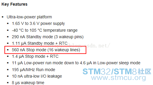
在ST官网的STM32L152RE芯片介绍上明确有说明此芯片在stop模式下可以达到560nA,纳安!并且还可以支持16个外部中断唤醒。

真的这么强!下面来验证一下。
采用NUCLEO-L152板子进行验证,使用CubeMx生成工程代码。
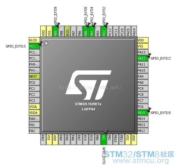
在CubeMx中选择STM32L152RE这款芯片,pinout如下设置:

如上图,只是简单地将PC13,PB9,PB5,PB4,PD2,PA12,PB15,PB1设置为外部中断。
为了得到最低功耗,时钟树采用芯片内部时钟HSI:

在configuration下,将GPIO都设置为下拉,PC13在NUCLEO板子上是按键,设为上拉。

生成代码。main函数稍作修改:
[cpp] view plain copy
- int main(void)
- {
-
- /* USER CODE BEGIN 1 */
-
- /* USER CODE END 1 */
-
- /* MCU Configuration----------------------------------------------------------*/
-
- /* Reset of all peripherals, Initializes the Flash interface and the Systick. */
- HAL_Init();
-
- /* Configure the system clock */
- SystemClock_Config();
-
- /* Initialize all configured peripherals */
- MX_GPIO_Init();
-
- /* USER CODE BEGIN 2 */
- HAL_PWREx_EnableUltraLowPower();
- HAL_PWREx_EnableFastWakeUp();
- /* USER CODE END 2 */
-
- /* Infinite loop */
- /* USER CODE BEGIN WHILE */
- while (1)
- {
- /* USER CODE END WHILE */
-
- /* USER CODE BEGIN 3 */
- HAL_PWR_EnterSTOPMode(PWR_LOWPOWERREGULATOR_ON, PWR_STOPENTRY_WFI);
-
- /* Configures system clock after wake-up from STOP: enable HSI, PLL and select
- PLL as system clock source (HSI and PLL are disabled automatically in STOP mode) */
- SystemClockConfig_STOP();
- HAL_Delay(200);
- }
- /* USER CODE END 3 */
-
- }
SystemClockConfig_STOP函数如下配置:
[cpp] view plain copy
- static void SystemClockConfig_STOP(void)
- {
- RCC_ClkInitTypeDef RCC_ClkInitStruct = {0};
- RCC_OscInitTypeDef RCC_OscInitStruct = {0};
-
- /* Enable Power Control clock */
- __HAL_RCC_PWR_CLK_ENABLE();
-
- /* The voltage scaling allows optimizing the power consumption when the device is
- clocked below the maximum system frequency, to update the voltage scaling value
- regarding system frequency refer to product datasheet. */
- __HAL_PWR_VOLTAGESCALING_CONFIG(PWR_REGULATOR_VOLTAGE_SCALE1);
-
- /* Poll VOSF bit of in PWR_CSR. Wait until it is reset to 0 */
- while (__HAL_PWR_GET_FLAG(PWR_FLAG_VOS) != RESET) {};
-
- /* Get the Oscillators configuration according to the internal RCC registers */
- HAL_RCC_GetOscConfig(&RCC_OscInitStruct);
-
- /* After wake-up from STOP reconfigure the system clock: Enable HSI and PLL */
- RCC_OscInitStruct.OscillatorType = RCC_OSCILLATORTYPE_HSI;
- RCC_OscInitStruct.HSEState = RCC_HSE_OFF;
- RCC_OscInitStruct.HSIState = RCC_HSI_ON;
- RCC_OscInitStruct.PLL.PLLState = RCC_PLL_ON;
- RCC_OscInitStruct.PLL.PLLSource = RCC_PLLSOURCE_HSI;
- RCC_OscInitStruct.HSICalibrationValue = RCC_HSICALIBRATION_DEFAULT;
- RCC_OscInitStruct.PLL.PLLMUL = RCC_PLL_MUL6;
- RCC_OscInitStruct.PLL.PLLDIV = RCC_PLL_DIV3;
- if(HAL_RCC_OscConfig(&RCC_OscInitStruct) != HAL_OK)
- {
- Error_Handler();
- }
-
- /* Select PLL as system clock source and configure the HCLK, PCLK1 and PCLK2
- clocks dividers */
- RCC_ClkInitStruct.ClockType = RCC_CLOCKTYPE_SYSCLK;
- RCC_ClkInitStruct.SYSCLKSource = RCC_SYSCLKSOURCE_PLLCLK;
- if(HAL_RCC_ClockConfig(&RCC_ClkInitStruct, FLASH_LATENCY_1) != HAL_OK)
- {
- Error_Handler();
- }
- }
编译烧录后使用电流表进行测试:

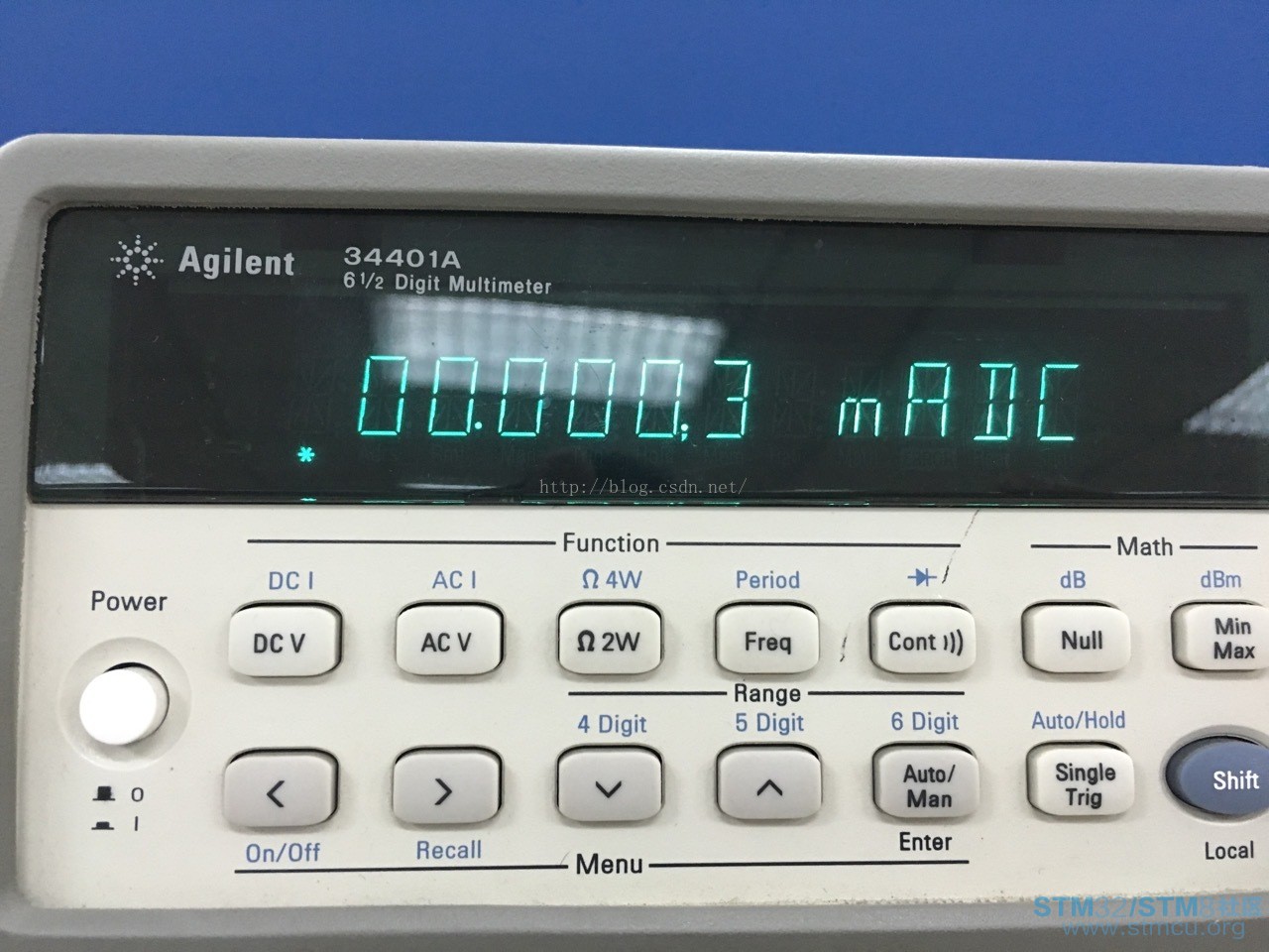
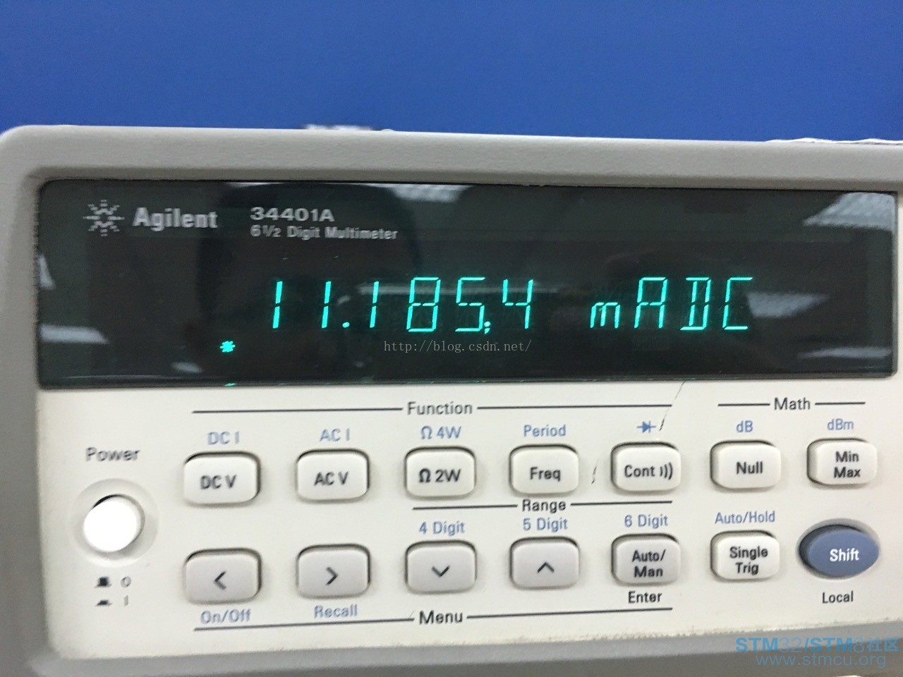
0.3uA! 看来所言非虚,300nA,按下按键,发现电流变大了,如下:

电流变为11mA,这个位为工作电流,这说明外部中断生效了。
STM32L152在低功耗这块,确实还不错!实测stop模式下300nA的电流,比手册上所示的560nA还低,看来ST还是比较保守。
转载自FLYDREAM0
|


 微信公众号
微信公众号
 手机版
手机版

谢谢分享