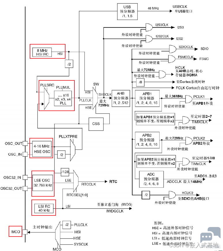



STM32时钟源介绍1. STM32的时钟源主要有:
HSI(内部高速时钟)
HSE(外部高速时钟)
LSI(内部低速时钟)
LSE(外部低速时钟)
PLL(锁相环)
MCO(时钟输出管脚)
首先打开startup_stm32f10x_hd.s,该文件为stm32的启动文件,在该文件内会发现有这么一块用汇编写的代码。 Reset_Handler PROC* c' w- n. _$ ]5 C6 b- A' tEXPORT Reset_Handler [WEAK] IMPORT __main IMPORT SystemInit LDR R0, =SystemInit BLX R0 8 i# D& k6 q; g LDR R0, =__main' `: ~5 Q( i2 S, A F BX R0 ENDP 通过这段汇编代码可以看出,程序在执行main函数之前,会先执行SystemInit函数。 2.2 SystemInit函数详解void SystemInit (void){% r0 ? G( P, k, h x /* Reset the RCC clock configuration to the default reset state(for debug purpose) */ /* Set HSION bit */2 `8 w; v% e2 v9 Q4 x RCC->CR |= (uint32_t)0x00000001; . J, ]4 f0 Z+ [$ i" W3 t /* Reset SW, HPRE, PPRE1, PPRE2, ADCPRE and MCO bits */ O: r# v' l! ?( V #ifndef STM32F10X_CL2 Z- v9 h% P' ]& i2 R, J( t RCC->CFGR &= (uint32_t)0xF8FF0000; #else RCC->CFGR &= (uint32_t)0xF0FF0000;; Y `: ^& K! m1 Y. e2 w/ } #endif /* STM32F10X_CL */ /* Reset HSEON, CSSON and PLLON bits */& T8 k3 o" X$ T" Y( h RCC->CR &= (uint32_t)0xFEF6FFFF; # s6 p, Y4 O( V# V) r /* Reset HSEBYP bit */ RCC->CR &= (uint32_t)0xFFFBFFFF; 5 X; X* |. r9 O2 |/ c. n7 q( u$ f9 m% F /* Reset PLLSRC, PLLXTPRE, PLLMUL and USBPRE/OTGFSPRE bits */" O* I8 r+ k3 m3 c& p RCC->CFGR &= (uint32_t)0xFF80FFFF;4 n6 E; j' e, p* y& {$ O5 F" e #ifdef STM32F10X_CL0 q7 M; p+ l- O+ \ /* Reset PLL2ON and PLL3ON bits */! Q& D4 g, v8 e: C5 M/ q, W RCC->CR &= (uint32_t)0xEBFFFFFF;: L; _' g6 k* c _/ v /* Disable all interrupts and clear pending bits */9 v' y% ~. N: u, M8 K/ Q/ y6 t RCC->CIR = 0x00FF0000; /* Reset CFGR2 register */ RCC->CFGR2 = 0x00000000;, u( ]& ^* p _/ H+ ?1 i #elif defined (STM32F10X_LD_VL) || defined (STM32F10X_MD_VL) || (defined STM32F10X_HD_VL); w& E* v( z$ P/ q /* Disable all interrupts and clear pending bits */ RCC->CIR = 0x009F0000; % H" {; h& _( a2 C; r /* Reset CFGR2 register */ RCC->CFGR2 = 0x00000000; #else /* Disable all interrupts and clear pending bits */ RCC->CIR = 0x009F0000;+ }- b7 R. a# P8 Z& \6 t. ^ #endif /* STM32F10X_CL */" X& L* V: N6 U- C7 g3 _ #if defined (STM32F10X_HD) || (defined STM32F10X_XL) || (defined STM32F10X_HD_VL), Z0 W# W% k+ w1 |' \& i$ c #ifdef DATA_IN_ExtSRAM4 a8 ~% W* R( O0 U; e- d4 z% c3 m SystemInit_ExtMemCtl(); % j; l* r% e1 C/ x' {9 A #endif /* DATA_IN_ExtSRAM */ #endif . Q, F# P. f/ e /* Configure the System clock frequency, HCLK, PCLK2 and PCLK1 prescalers */: j- K' z; T/ t) W3 S) A /* Configure the Flash Latency cycles and enable prefetch buffer */ SetSysClock(); {$ S, v' w* t( [, b5 n I #ifdef VECT_TAB_SRAM. O# g8 A" D7 {: z9 h SCB->VTOR = SRAM_BASE | VECT_TAB_OFFSET; /* Vector Table Relocation in Internal SRAM. */ #else& @1 x& Y, g+ e' u% Q, ]- | SCB->VTOR = FLASH_BASE | VECT_TAB_OFFSET; /* Vector Table Relocation in Internal FLASH. */* }( x- d- q! f #endif , |# o& N/ [6 \) G" w/ s } 打开内部8M时钟RCC->CR |= (uint32_t)0x00000001 通过查看寄存器手册可知,这段代码为打开内部8M时钟。

设置时钟配置寄存器#ifndef STM32F10X_CL% u6 `# h1 d4 B/ M RCC->CFGR &= (uint32_t)0xF8FF0000; #else; M2 d+ t; F+ y3 w2 ?8 O( I RCC->CFGR &= (uint32_t)0xF0FF0000;/ G6 J3 k$ \' ]$ P9 q #endif /* STM32F10X_CL */ 对应寄存器说明可查看《STM32中文参考手册_V10》的6.3.2 时钟配置寄存器(RCC_CFGR)章节。 后续代码,有兴趣可根据《STM32中文参考手册_V10》手册,查看代码具体作用。 2.3 SetSysClock()函数详解static void SetSysClock(void); S* o) N* f$ T% r{ #ifdef SYSCLK_FREQ_HSE SetSysClockToHSE(); #elif defined SYSCLK_FREQ_24MHz SetSysClockTo24();0 V" h% t4 m6 L! @5 Y, Z% \ A9 i# Z #elif defined SYSCLK_FREQ_36MHz0 a. C0 a. f3 q SetSysClockTo36();4 W6 }2 Y4 l& X9 ` #elif defined SYSCLK_FREQ_48MHz SetSysClockTo48();( \) V3 |3 r3 g9 U/ V5 `( r) c #elif defined SYSCLK_FREQ_56MHz SetSysClockTo56(); ; i/ _# q. T" z! f1 h( j! J #elif defined SYSCLK_FREQ_72MHz3 ~# j1 N Z& h SetSysClockTo72();, L. m/ z0 d. ?4 _) O# S* W: A #endif } system_stm32f10x.c文件中会根据芯片的型号定义对应的宏 #if defined (STM32F10X_LD_VL) || (defined STM32F10X_MD_VL) || (defined STM32F10X_HD_VL)/* #define SYSCLK_FREQ_HSE HSE_VALUE */ #define SYSCLK_FREQ_24MHz 24000000 #else! Q; q' V% P. [2 R/ g+ B- B /* #define SYSCLK_FREQ_HSE HSE_VALUE */7 a7 I, ^- Y) u- Q /* #define SYSCLK_FREQ_24MHz 24000000 */ /* #define SYSCLK_FREQ_36MHz 36000000 */ /* #define SYSCLK_FREQ_48MHz 48000000 */ /* #define SYSCLK_FREQ_56MHz 56000000 */ #define SYSCLK_FREQ_72MHz 720000003 r' E9 H& U: l4 R3 J #endif 3. 时钟配置函数3.1 时钟初始化配置函数void SystemInit(void);, {1 p" r( G% Z6 F SYSCLK(系统时钟)=72MHZ; AHB总线时钟(HCLK=SYSCLK)=72MHZ;/ C; E& K5 }& ?- g* P! J APB1总线时钟(PCLK1=SYSCLK/2)=36MHZ;: m* {: Y! M' ~ APB2总线时钟(PCLK1=SYSCLK/1)=72MHZ;7 |4 E u& ^, ~7 p1 A# V PLL主时钟=72MHZ; 3.2 外设时钟使能配置函数void RCC_AHBPeriphClockCmd(uint32_t RCC_AHBPeriph, FunctionalState NewState);. A1 \ o' {9 g void RCC_APB2PeriphClockCmd(uint32_t RCC_APB2Periph, FunctionalState NewState); void RCC_APB1PeriphClockCmd(uint32_t RCC_APB1Periph, FunctionalState NewState); 3.3 时钟源使能函数void RCC_HSICmd(FunctionalState NewState);, {2 S/ c# P7 f% ?- \2 I void RCC_LSICmd(FunctionalState NewState); void RCC_PLLCmd(FunctionalState NewState);+ b0 S5 q) C/ c. j; x/ e2 i. n, s void RCC_RTCCLKCmd(FunctionalState NewState); 3.4 时钟源和倍频因子配置函数void RCC_HSEConfig(uint32_t RCC_HSE); void RCC_SYSCLKConfig(uint32_t RCC_SYSCLKSource);2 w4 E% z. o" i4 M8 C2 r void RCC_HCLKConfig(uint32_t RCC_SYSCLK);* q/ B( I) Z, x3 Y% [ void RCC_PCLK1Config(uint32_t RCC_HCLK); void RCC_PCLK2Config(uint32_t RCC_HCLK);5 h. a& n. f+ b; B5 q2 c 3.5 外设时钟复位函数void RCC_APB2PeriphResetCmd(uint32_t RCC_APB2Periph, FunctionalState NewState);; u: s o7 [" y7 z! L- T$ B5 x& Y void RCC_APB1PeriphResetCmd(uint32_t RCC_APB1Periph, FunctionalState NewState); 3.6 自定义系统时钟void RCC_HSE_Config(u32 div,u32 pllm) { RCC_DeInit(); RCC_HSEConfig(RCC_HSE_ON);* q. V1 ]% t1 Q if(RCC_WaitForHSEStartUp()==SUCCESS)4 n9 F, c" ^9 R0 `9 a { RCC_HCLKConfig(RCC_SYSCLK_Div1);5 Q- I) n2 l( r( a B4 o RCC_PCLK1Config(RCC_HCLK_Div2);6 E! ?6 ]0 ^" X) B( v RCC_PCLK2Config(RCC_HCLK_Div1);2 a6 B5 Z9 o% W( l2 \ RCC_PLLConfig(div,pllm);! l) k- y. N3 g3 {- a# R( C p, n4 ? RCC_PLLCmd(ENABLE); 5 S( q1 _) t( n; Q while(RCC_GetFlagStatus(RCC_FLAG_PLLRDY)==RESET) RCC_SYSCLKConfig(RCC_SYSCLKSource_PLLCLK) while(RCC_GetSCLKSource()!=0x08); }, q3 Z- d8 t4 k; X, U } |
 微信公众号
微信公众号
 手机版
手机版