|
本帖最后由 anobodykey 于 2017-12-26 16:40 编辑 In this article I will tell about how it is possible to take analog black-and-white video signal by means of STM32F4-DISCOVERY payment, and about features of its transfer on the computer by means of USB. Transfer of images on the computer on USB Using STM32F4-DISCOVERY payment, it is possible to create different USB devices — the peripheral USB module in the used microcontroller has big functionality. And here it is not enough examples of unusual constructions with its use in a network — in most cases USB use for implementation of the classes HID (emulation of keyboards, mice and dzhoystiv) and CDC (emulation of COM port). The built-in USB-host is usually used for connection of USB USB sticks. I wanted to make any unusual USB device, for example, the webcam. It is possible to implement it in two ways — to write an own class of the USB device, and the driver for it, or, what is much simpler, to use standard for an USB class of UVC video devices (USB video device class). Drivers for such devices are built in even the Windows XP. The main description on UVC can be found in this document (I used the UVC 1.0 version though is also newer 1.1). It is not enough UVC examples of implementation on the microcontroller on the Internet. Rather big complexity is represented by the correct drawing up descriptors of the device (descriptors describe all its functionality). Even the small error in a descriptor can lead to the fact that the device will appear will be defined, or even to BSOD. It is possible to copy descriptors from the available webcam, however they can be excessively difficult — cameras often contain the microphone, allow to make capture of the single image (Still image capture in UVC terminology), allow to change a large number of settings of the camera. In all this it is easy to get confused so I wanted to make the simplest project. After long searches, absolutely accidentally came across such Chinese project. It is a tetris for STM32F103, and for display of the picture the computer which sees the controller as the UVC device is used. In the project even coding of MJPEG is implemented. The project is quite interesting, but the code which there is incredibly confused with almost total absence of comments. I took descriptors from it, and corrected them under the requirements a little. By drawing up descriptors, among other things, it is necessary to specify parameters of the transferred image. I stopped on image size in 320x240 pixels and NV12 image format. The UVC standard allows to betray only two formats of uncompressed images: NV12 and YUY2. The second format is more widespread, but NV12 is suitable for coding of black-and-white images more and takes less places. In this format data are coded as YUV 4:2:0 (two bytes of the color information are the share of four pixels). At first there is brightness information of all image (320*240 bytes in my case), then the color information (in turn there are bytes of U and V): In total image will occupy (320*240*3/2) bytes. This format has a shortcoming — not all programs are able to work with it. With guarantee the free program ContaCam, Skype works with this format too worked normally. To load test images into the controller, the special converter issuing.h files with the coded picture data was written. Except NV12, the converter can code images in the YUY2 format. The detailed description of how it is correct to configure descriptors and to transfer a data stream in case of uncompressed images, it is possible to find in the separate document: "Universal Serial Bus Device Class Definition for Video Devices: Uncompressed Payload" As the basic project I am taken the project of the USB microphone. In it data transmission on the computer through an isochronous ending point was implemented too. Work with USB is implemented by means of library from the vendor of the controller (STSW-STM32046). After replacement of descriptors, VID/PID (as I understood, it is possible to set any), the controller was found as the processing device of images. The following stage — transfer on the video information flow computer (for a start — the test image which is stored in memory of the controller). Previously it is worth mentioning different USB requests (Request) which need to be processed. When obtaining by the request controller from the computer (host) of some types of requests, the USB library causes the usbd_video_Setup function which has to process request. The most part of this function is taken from a microphone code - it is processing of Standard Device Requests. Here it is possible to pay attention to switching between alternative interfaces which occurs at receipt of request of SET_INTERFACE. The UVC device has to provide at least two alternative interfaces of which (Zero Bandwidth, goes at 0 number) the computer switches the USB device when it is not necessary to one, thereby limiting a data stream on the bus. When any program on the computer is ready to accept data from the device, it transfers to it request for switching for other alternative interface then the device begins to receive from a host of IN Token Packets, signaling that the host expects data transmission. There is also other type of requests — Class Device Requests specific to this class — UVC. They are used for obtaining from the camera of data on its status and management of its work. But even in the elementary implementation when no parameters of the camera can be changed, the program has to process requests: GET_CUR, GET_DEF, GET_MIN, GET_MAX, SET_CUR. All of them are given before turning on of the camera from the computer. According to the UVC specification, the computer requests the modes in which she is able to work from the camera, and then transfers the instruction in what mode the camera has to work. And there are two types of such requests: Probe and Commit. In my case, these data are not used in any way, but if not to process request (not to take away the sent data or not to answer), then the program on the computer "will hang up", and the controller will need reset. In the course of creation of the project it was found out that the USB library sometimes incorrectly processes requests of data transmission for a host — after transfer of some small data volume data transmission stops and to renew it it is only possible to reboot. It concerns as transfer of a video information (through 1 ending point), and control data (through 0 ending point). It improves preliminary cleaning of FIFO of the necessary ending point before record in it. After all necessary requests are transferred, and the computer sent a request for switching of the alternative interface in the main mode, it is possible to begin to transfer video data. The computer begins to issue on the bus IN Token Packet each millisecond when which obtaining the controller causes the usbd_video_DataIn function from which it is necessary to cause library function of data transmission of DCD_EP_Tx. Video data are transferred by packets, at the beginning of each packet has to there is a heading 2 bytes long (the UVC specification supports use and longer headings with additional information). The first byte of heading is always equal 2 - it is the total length of heading. The second byte allows a host to find the beginning of a frame and their change — the first bit of this byte needs to be switched in the first packet of a new frame. In the subsequent packets of this frame value of this bit has to remain same. It is possible to leave other bits equal to zero. The rest of a packet is occupied by video data. Their length in a packet can be any (but no more certain size). I specially selected length of video data in a packet such that image size in bytes was divided into it without remaining balance — so all packets turn out identical length. Such result turns out here: And what with a performance? The controller supports the USB Full Speed standard that gives the theoretical speed of 12 Mbps. Thus, at most, what it is possible to expect — transmission time of a frame will be (320*240*3/2) / (12*10^6/8) = 76 ms that gives 13 FPS. However, USB — the half-duplex protocol, and the microcontroller has the restrictions. Transfers data on the USB controller with use of FIFO, and this memory at the controller — 1250 bytes, and it needs to be separated between all control points. Distribution of memory is specified in the usb_conf.h file, and the sizes are specified in 32-bit words. #define RX_FIFO_FS_SIZE 64 #define TX0_FIFO_FS_SIZE 16 #define TX1_FIFO_FS_SIZE 232 #define TX2_FIFO_FS_SIZE 0 #define TX3_FIFO_FS_SIZE 0 For FIFO of acceptance of commands from the computer it is necessary to select not less than 64 words, on FIFO of a predacha of control data on the computer through 0 ending point 16 more words are necessary. All the rest can be selected for the first finishing point for transfer of video data. Totally it turns out (64 + 16 + 232)*4 = 1248 bytes. As there is a restriction for the 232nd word (928 bytes), the packet size (VIDEO_PACKET_SIZE) was set equal (768+2) bytes. Thus, one frame consists from (320*240*3/2) / (768) = 150 packets which will indulge 150*1ms that gives 6,6 FPS. The real result matches calculated: Not really there is a lot of, but by transfer of the uncompressed image at the same size bigger not to receive. Therefore I decided to try to squeeze the image on the microcontroller. Transition to MJPEG The UVC standard supports different types of compression, one of which — MJPEG. In this type of compression each initial video frame contracts according to the JPEG standard. The received compressed frame can be sent to the computer as it is described above. Features of descriptors and data transmission for MJPEG are described in the document "by Universal Serial Bus Device Class Definition for Video Devices: Motion-JPEG Payload". Transfer of the freeze frame image prepared on the computer it turned out quite simple — the normal JPEG file in.h the file is convertible, we add it to the project, we transfer him on packets, also as before. As the size of the compressed image can be any, length of the last data packet turns out too variable so it needs to be calculated. At the size of the compressed image of 30000 bytes, it will consist from (30000/768) => 40 packets which will be told 40 ms that corresponds to 25 FPS. For compression in JPEG I decided to use the encoder taken here. It is adapted for ARM, and expected only the black-and-white image that suited me, so so I was going to take data from the black-and-white camera. This encoder earned from STM32F4 at once, I did not do any adaptation under Cortrx-M4. Test bmp the file contracted for 25 ms that corresponds to 40 FPS. To consider the compressed image from the controller, I used the STM32 ST-LINK Utility program. Previously during debugging of the program it is necessary to learn a starting address of an array in which the compressed image will be located, and then to specify it in this program. The read dump can be saved as .jpg at once. Further I added in the encoder a feature for work with two output arrays — for double buffering, and integrated him with the project of a data output on USB. Feature of use of memory of CCMIn the used RAM controller it is separated into several blocks. One of them — (64 Kb) is called CCM, and it is impossible to get access through DMA to it. I decided to place two arrays for storage of the compressed image here. To use this memory, in IAR it is necessary to edit the file used by .icf, having added to it a line: define symbol __ICFEDIT_region_RAMCCM_start__ = 0x10000000;define symbol __ICFEDIT_region_RAMCCM_end__ = 0x1000FFFF;.......define region CCMRAM_region = mem:[from __ICFEDIT_region_RAMCCM_start__ to __ICFEDIT_region_RAMCCM_end__];.......place in CCMRAM_region {section .ccmram}; It is necessary to declare arrays in a code so: #pragma location = ".ccmram"uint8_t outbytes0[32000];#pragma location = ".ccmram"uint8_t outbytes1[32000]; The turned-out construction earned, however only in the ContaCam program and in the browser (it was checked here). On the freeze frame image it was succeeded to receive 35 FPS. Example of the compressed image (image size of 17 Kb): The image is inverted as information files is stored in bmp quite so. And here other programs either did not work at all, or gave here such image: It is connected with the fact that the UVC standard does not support transfer of black-and-white images by means of MJPEG. Requirements in JPEG to the image such: • Color encoding — YCbCr Thus, the available encoder for forming of pseudo-color images was required to remake — on the present in such image only data on brightness (Y), and instead of data on color are coded (Cb and Cr) are transferred zero. It was necessary will get acquainted with structure of the JPEG format more deeply. Transition from the black-and-white image to pseudo-color As the encoder worked earlier: 1. The file heading JPEG forms. 2. Block (8x8 pixels) processing of the source image. 2.1 Each block is read out from memory, its discrete cosine transform (DCT) is made 2.2 The turned-out 64 values are quantized and the result is packed with use of Huffman codes. 3. The marker of the end of data forms and the size of the compressed image is counted. In more detail about JPEG it is possible to esteem here and here. Information on existence of color in the compressed image is stored in the heading JPEG so it needs to be changed. It is necessary to change the sections SOF0 and SOS, having specified in them use of three components, for the brightness component thinning 22, for color 11. Everywhere I specified 0 as the identifier of quantizing tables. Now it is possible to change a data coding technique. As color information is coded with thinning, to two color information blocks there have to correspond four blocks of the brightness information. Thus, at first four blocks of the brightness information then it is necessary to make coding of two more blocks of color information (an example from the above-stated article) are consistently coded: In the used library quantization, final compression of the processed data, and record them in memory are executed by separate function so for forming of color information it is enough to nullify an array of DCT of coefficients and to cause this function twice. However in JPEG coding there is an important feature — not the DC coefficients going at the beginning of each block, but a difference of the current DC coefficient, and DC coefficient of the previous block of a matching component are coded. In library this difference was initially calculated before quantization so it was necessary to modify the above-stated function so that during processing of Cr and Cb channels the difference was not calculated — in these components and so there are zero. As a result the picture began to be displayed correctly in all used programs of video capture. A lack of such pseudo-color coding — its speed fell a little. Compression test the image began to occupy 35 ms that gives 28 FPS. Capture of analog video signal Now, when the method appeared to transfer video data to the computer with an acceptable speed, it is possible to be engaged also in capture of video signal. From the very beginning of experiments with USB I assumed to implement capture of video signal from an analog video camera means of the most debug payment. As earlier I already did the self-made TV on the microcontroller, the technique of capture of black-and-white video signal was not for me something new. Of course, the STM32F4 controller strongly differs from ATxmega so also approach to capture of video had to be changed. The PAL format is already repeatedly described on different resources so I will stop on its basic provisions, and only for black-and-white option. Frame frequency of this format — 25 Hz, but at the same time is used interlaced scan — that is by transfer of a frame at first even, and then odd lines are transferred at first. Each such rowset is called a field. Fields in this format go with a frequency of 50 Hz (20 ms). 312,5 lines (from them only 288,5 contain a video information) are transferred in one field. All lines are separated by clock pulses which follow with the period of 64 microsec. Video signal in line at the same time occupies 52 microsec. Fields are separated by the personnel and equalizing clock pulses. Important feature of the equalizing clock pulses — their period is twice less than the period of lines — 32 microsec so it is easy to distinguish them from clock pulses. Thus, to take the image in memory of the controller, it is necessary to write the program capable to find synchronization signals, to select from them equalizing pulses and to start the ATsP conversion in before transfer of video data of every line. Now follows will dwell upon a video signal digitization technique. In the STM32F4 controller are available three separate ATsP, each of which can work with speed of 2.4 MSPS at digit capacity of 12 bits. At digit capacity reduction the speed of work increases, but also it will not be enough for receipt of permission 320*240. However the controller allows to integrate several ATsP — it is possible to configure capture of ATsP by all at the same time, and it is possible to set a capture delay between ATsP therefore the general capture rate increases. What capture rate will be when using of two ATsP (Interleaved dual mode) at once? For clocking of ATsP the bus APB2 which clock frequency at initialization of the controller is established by a wound to a half of system frequency (168 MHz/2) = 84 MHz is used. For ATsP it is too much so at the ATsP setup it is necessary to set a predivider on 2. The turned-out frequency of 42 MHz all the same is more maximum admissible on a datashita (36 MHz), but my ATsP well works also with such frequency. If each ATsP at the set digit capacity of 8 bits would work separately, the maximum speed of conversion would be (42 MHz / (3+8)) = 3.81 MSPS. Having set a delay between time of capture of data in 6 cycles, it is possible to receive the speed 7 MSPS, and at 7 cycles — 6 MSPS. I selected the last option. At the same time it turns out that all line (64 microsec) will occupy 384 bytes, and the active part of a line with video signal (52 microsec) will occupy 312 bytes (pixels). ATsP transfers results of conversion to memory by means of DMA. When using two 8-bit ATsP, data are transferred to memory in the form of 16-bit words at the time of completion of conversion of the second ATsP. In principle, it would be possible to take in memory contents practically of all frame entirely — (384*240) = 92,16 Kb for this purpose are necessary. But I went on other way — capture of data begins the sync controller after detection, and stops after capture of 366 bytes (183 DMA broadcasts). Why such number is selected — I will tell further. As a result video data occupy (366*240) = 87,84 Kb of OZU. Let's consider a technique of detection of a synchronization signal. Ideally, it is better to find it a special chip, or at least the comparator, but it complicates construction. As I had one not used ATsP, I decided to apply it to detection of synchronization signals. The special module "Analog watchdog" is a part of each ATsP. It can create interruption if the digitized value goes beyond the set limits. However this module is not capable to react to change of the front of the digitized signal — it will create interruption until the input signal or settings of the module changes. As I needed to find fronts of a signal, it was necessary to make reconfiguration of this module at each its interruption. I did not begin to implement automatic detection of thresholds of operation of Analog watchdog so they are specified manually for the used camera in the program. To find equalizing pulses, one of controller timers working with frequency of 1 MHz is used. The timer works constantly, and in the processor of interruption of Analog watchdog (at detection of leading edge of clock pulse) its current value is read out, and compared to previous. Thus it is possible to distinguish lower case clock pulses from equalizing. After the equalizing clock pulses ended, the controller misses 17 lower case clock pulses, and at detection of leading edge of clock pulse begins capture of video data of the current line. As the input in the processor of interruption in this controller can can occur for variable time, and also because ATsP 3 works more slowly, than the first two together, time between clock edge and the beginning of capture can will cause a stir that leads to "trembling" of lines. For this reason capture of video data begins with leading edge of clock pulse, and the line occupies 366 bytes — thus the part of clock pulse gets into the shot, and she can be moved away programmatically for every line. On the oscillogram it is visible how there is a video signal capture (during operating time of DMA "yellow" the channel is installed in 1): Capture begins only after emergence of video data: Not all lines in one field are taken as restriction in 240 lines is set. As a result such unprocessed image turns out here (it is received with use of ST-Link Utility): After the image is taken in memory of the controller, it needs to be processed — for every line to clean the shift connected with capture of a synchronization signal and to subtract black level value from values of brightness of pixels. I did not try to optimize this code location so its execution occupies 5 ms. After the image is processed, it can begin to be coded in JPEG, at the same time transfer on USB of already coded data of the previous image at the same time begins. Thus, the frame is taken 20 ms, processing goes 5 ms, and coding together with data transmission there are 35 ms that totally gives 60 ms, or picture frequency 16.6 of FPS. As a result it turns out that one frame (actually a field) is taken, and two are passed. As development in the PAL format interlaced, comes out that in turn are taken that even, that odd field that leads to a picture jitter on one pixel. Will get rid of it it is possible, having added an additional delay between capture of frames — one more field will be passed then, and picture frequency on an output will fall to (50/4) = 12.5 FPS. It is a little about video source Initially I was going to use as a signal source a video camera of video surveillance of KPC-190S (this camera nearly 15 years). It is impossible to tell that it provides high quality of the image — it rather noisy, with not really high contrast, and small amplitude (from the oscillogram it is visible that it is close to 1 V). For small fine tuning of a signal output the camera is connected to the controller through a resistor divider on the variable resistor. The only signal output of a payment to which the camera is connected is PC2 (ATsP are connected to it all). Appearance of construction: 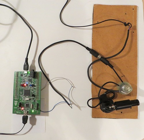 As the camera did not provide the high quality image, I decided to try to take a signal from the Canon A710 camera. It has an analog output for connection to the TV to which everything that is displayed on the camera screen is brought. Signal quality at the camera is better, however video signal at it color. To clean a color component from a signal, I used here such filter: Besides, clock pulses on an output of the camera have negative polarity so in order that they were found controller ATsP, it was necessary to add to a signal additional bias voltage by means of the regulated power supply. Also it was necessary to change thresholds of operation of Analog watchdog a few. Appearance of construction with the connected camera: 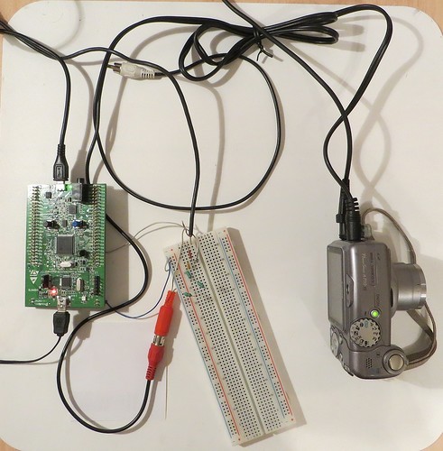 Example of the image received from the camera: Video of operation of the device: Source codes of projects: github.com/iliasam/STM32F4_UVC_Camera
原文链接:http://geek-mag.com/posts/255316/ |
【福利三:雨露均沾·逢7狂欢】之四:用一个定时器同步另外两个定时器输出PWM
【逢7发帖赢大礼】STM32开发之WIFI实时时钟
【逢7发帖赢大礼】STM32开发之指纹识别!
【逢7发帖赢大礼】STM32开发之环境空气质量监测
【逢7发帖赢大礼】STM32开发之人体实时运动信息监测!
【逢7发帖赢大礼】STM32开发之IC门禁卡UID读取方法!
【逢7发帖赢大礼】全网最简单的Arduino_STM32开发环境搭建教程!
STM32F4中文用户手册
STM32F400、STM32F402 Cortex-M4超值单片机
SPI 高温读错最后一位?STM32F42xx 官方根治方案
 微信公众号
微信公众号
 手机版
手机版


