


.png) STMCU小助手
发布时间:2022-1-31 15:00
STMCU小助手
发布时间:2022-1-31 15:00
|
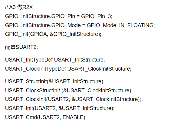
使用查询方式的USART: 设置时钟: RCC_APB2Periph_AFIO 功能复用IO时钟 RCC_APB2Periph_GPIOA GPIOA时钟 RCC_APB2Periph_USART1 USART1时钟 你可以用 //使能串口1,PA,AFIO总线 RCC_APB2PeriphClockCmd (RCC_APB2Periph_GPIOA|RCC_APB2Periph_AFIO|RCC_APB2Periph_USART1 ,ENABLE); 或直接 RCC_APB2PeriphClockCmd(RCC_APB2Periph_ALL,ENABLE); //全部APB2外设时钟开启 注意USART2的你开启为 RCC_APB1PeriphClockCmd(RCC_APB1Periph_USART2,ENABLE); 设置GPIO: GPIO_InitTypeDef GPIO_InitStructure; GPIO_InitStructure.GPIO_Pin = GPIO_Pin_9; GPIO_InitStructure.GPIO_Speed = GPIO_Speed_50MHz; GPIO_InitStructure.GPIO_Mode = GPIO_Mode_AF_PP; //推挽输出-TX GPIO_Init(GPIOA, &GPIO_InitStructure); GPIO_InitStructure.GPIO_Pin = GPIO_Pin_10; GPIO_InitStructure.GPIO_Mode = GPIO_Mode_IN_FLOATING; //浮空输入-RX+ x. Z0 L+ [9 F GPIO_Init(GPIOA, &GPIO_InitStructure); 设置USART: 这里我用的是3.0的库相对于2.0的库来说多了一步,先说2.0 USART_InitTypeDef USART_InitStructure; USART_StructInit(&USART_InitStructure); //装填默认值 USART_Init(USART1, &USART_InitStructure); //根据USART_InitStruct中指定的参数初始化外设USARTx寄存器 USART_Cmd(USART1, ENABLE); //启用 就好了~! 而3.0的库需要 USART_InitTypeDef USART_InitStructure; USART_ClockInitTypeDef USART_ClockInitStructure; USART_StructInit(&USART_InitStructure); USART_ClockStructInit (&USART_ClockInitStructure); USART_ClockInit(USART1, &USART_ClockInitStructure); USART_Init(USART1, &USART_InitStructure); USART_Cmd(USART1, ENABLE); //只是多分出了1个 USART_ClockInitStructure 我也不知为啥要这样??为了同步异步模式?USART_InitStruct中指定的参数内容为:(2.0的) typedef struct { _1 ^# t) V, u3 V* N u32 USART_BaudRate; //USART传输的波特率 u16 USART_WordLength; //一个帧中传输或者接收到的数据位数通常是82 j+ E$ h6 ]2 q; `5 H# |% r$ E" s u16 USART_StopBits; //停止位8 ?0 e1 n2 A4 I* \5 ?1 r u16 USART_Parity; //奇偶校验9 ^8 ~0 v6 G7 m# ^$ B u16 USART_HardwareFlowControl; //硬件流控制模式使能还是失能0 [3 T$ I x& u) z( Y9 g" K u16 USART_Mode; //指定了使能或者失能发送和接收模式 u16 USART_Clock; //提示了USART时钟使能还是失能2 Y0 |& H6 I% @6 O" z1 Y u16 USART_CPOL; //指定了下SLCK引脚上时钟输出的极性! o: h" c f5 H. o( W u16 USART_CPHA; //指定了下SLCK引脚上时钟输出的相位 u16 USART_LastBit; //来控制是否在同步模式下,在SCLK引脚上输出最后发送的那个数据字通常用USART_LastBit_Disable' l- }2 T, F% `) {1 O } USART_InitTypeDef; 我靠~!太细了~!我只知道(9600,8,n,1)这就够了 其他的统统默认~! USART_StructInit(&USART_InitStructure);) f4 N5 G# D5 @ USART_ClockStructInit (&USART_ClockInitStructure); //2.0不用这句,这样就设好了好了~!自动为您装填了默认参数。默认的参数如下(3.0的库): void USART_StructInit(USART_InitTypeDef* USART_InitStruct)5 Y. q% P" `" g! y; N* a/ N7 |9 p- I {, ^4 {- E" U" ^ USART_InitStruct->USART_BaudRate = 9600; USART_InitStruct->USART_WordLength = USART_WordLength_8b; USART_InitStruct->USART_StopBits = USART_StopBits_1; USART_InitStruct->USART_Parity = USART_Parity_No ; USART_InitStruct->USART_Mode = USART_Mode_Rx | USART_Mode_Tx;- `0 h# v' U1 i USART_InitStruct->USART_HardwareFlowControl = USART_HardwareFlowControl_None; 6 s Y) [9 d ~+ V: i } void USART_ClockStructInit(USART_ClockInitTypeDef* USART_ClockInitStruct) { USART_ClockInitStruct->USART_Clock = USART_Clock_Disable;, ^, K, N$ l U9 o" F USART_ClockInitStruct->USART_CPOL = USART_CPOL_Low; USART_ClockInitStruct->USART_CPHA = USART_CPHA_1Edge;5 x# L, [! v1 s+ @9 i USART_ClockInitStruct->USART_LastBit = USART_LastBit_Disable; } /************************************************************************************************/ 当然了你也可以自己设参数,比如这样。 void USART_Configuration(void) { USART_InitTypeDef USART_InitStructure;1 p" c7 d: Q3 h( I9 h7 M" F! v( v USART_ClockInitTypeDef USART_ClockInitStructure; USART_InitStructure.USART_BaudRate = 9600;7 }( Z, F9 P$ O% G% s! J+ } USART_InitStructure.USART_WordLength = USART_WordLength_8b; USART_InitStructure.USART_StopBits = USART_StopBits_1; USART_InitStructure.USART_Parity = USART_Parity_No;( n- U. o7 \0 }, T/ K USART_InitStructure.USART_HardwareFlowControl = USART_HardwareFlowControl_None;! O" {) s9 D ?; `8 X+ i) D USART_InitStructure.USART_Mode = USART_Mode_Rx | USART_Mode_Tx;7 Y/ S9 I" w' m USART_ClockInitStructure.USART_Clock = USART_Clock_Disable;" y% V+ y" u( D4 g& F5 t USART_ClockInitStructure.USART_CPOL = USART_CPOL_Low; j( c' Z/ `/ g6 b; [$ u( p USART_ClockInitStructure.USART_CPHA = USART_CPHA_2Edge;" |) y" R) w" G0 f$ _7 K: N+ Q USART_ClockInitStructure.USART_LastBit = USART_LastBit_Disable; USART_ClockInit(USART1, &USART_ClockInitStructure); USART_Init(USART1, &USART_InitStructure); USART_Init(USART1, &USART_InitStructure); USART_ClockInit(USART1, &USART_ClockInitStructure); USART_Cmd(USART1, ENABLE); } ////USART_ClockInitStructure.USART_CPHA= USART_CPHA_2Edge;除了这句以外其他的都和默认的参数一样,二者有啥区别我至今也不太清楚但就一般的应用来说两个都可以正常工作。 收发的方法: 1.发送 void USART1_Puts(char * str)3 e& a/ h, L, }, l# d6 x0 Z+ o {- t5 F# `& Q( ]6 Y) p+ j, g while(*str)9 o" X* F* J* B7 a9 @* N, X! v {0 m, f. o8 g# X: j7 u USART_SendData(USART1, *str++); while(USART_GetFlagStatus(USART1, USART_FLAG_TXE) == RESET); {3 I3 s0 B7 L) d- {- b# _3 F } } USART1_Puts("hello-java~!\r\n"); //这样就发送了hello-java~! 跟C语言的printf不太一样在于\n 并没有另起一行要用个\r这样在终端上好看。 2.接收 u8 uart1_get_data; //存放接受的内容 while(1) { if(USART_GetFlagStatus(USART1,USART_IT_RXNE)==SET) { uart1_get_data = USART_ReceiveData(USART1); USART1_Puts("\r\n获取到串口1数据:"); USART1_Putc(uart1_get_data);- P. r4 D0 _0 W! e USART1_Puts("\r\n"); } } 查询法的可以看出要不断扫描不是很好,下面介绍中断法。 首先配置时钟:这里我拿USART2说事: RCC_APB1PeriphClockCmd(RCC_APB1Periph_USART2,ENABLE); //USART2和USART3都在在APB1上而USART1是在APB2上的 设置GPIO: GPIO_InitTypeDef GPIO_InitStructure; RCC_APB2PeriphClockCmd(RCC_APB2Periph_GPIOA | RCC_APB2Periph_AFIO |ENABLE); // A2 做T2X GPIO_InitStructure.GPIO_Pin = GPIO_Pin_2;( ^8 B3 g- _! a9 }/ t) w GPIO_InitStructure.GPIO_Speed = GPIO_Speed_50MHz;1 z% a; t( P4 M$ j, n* } GPIO_InitStructure.GPIO_Mode = GPIO_Mode_AF_PP; GPIO_Init(GPIOA, &GPIO_InitStructure); // A3 做R2X% N+ G6 g! g, ?* f0 _! N4 l GPIO_InitStructure.GPIO_Pin = GPIO_Pin_3; GPIO_InitStructure.GPIO_Mode = GPIO_Mode_IN_FLOATING;- f% d' C2 D; ]* p5 f" W, a GPIO_Init(GPIOA, &GPIO_InitStructure); 配置SUART2: USART_InitTypeDef USART_InitStructure;0 N* U) p2 f. d' @$ T* U% J USART_ClockInitTypeDef USART_ClockInitStructure; USART_StructInit(&USART_InitStructure);; ~. H$ e1 \- y, u1 U USART_ClockStructInit (&USART_ClockInitStructure); USART_ClockInit(USART2, &USART_ClockInitStructure); USART_Init(USART2, &USART_InitStructure); USART_Cmd(USART2, ENABLE); |
实战经验 | 基于STM32G0B1的全桥移相+同步整流PWM解决方案
DMA 原理从 0 到 1:为什么它能解放 CPU?一文讲透 DMA 的工作流程
【福利三:逢7发帖赢大礼】8、基于STM32G070板子的Ymodem串口协议IAP Bootloader开发
【福利三:逢7发帖赢大礼】7、基于STM32G070板子TF卡的FATFS移植
【福利三:逢7发帖赢大礼】6、基于STM32G070板子spiflash的FATFS移植
【福利三:逢7发帖赢大礼】5、基于STM32G070板子IRDA红外遥控接收解码
【福利三:逢7发帖赢大礼】4、基于STM32G070板子SPI flash 移植SFUD库
【福利三:逢7发帖赢大礼】基于STM32G070板子的uart shell移植设计
【福利三:逢7发帖赢大礼】3、基于STM32G070板子的YModem串口协议通信
【福利三:逢7发帖赢大礼】2、基于STM32G070板子的OLED移植U8G2库
 微信公众号
微信公众号
 手机版
手机版