一.前言
Proprietary Code Read Out Protection (PCROP) ----- 专有代码读取保护
现在产品开发过程中,二次开发将会越来越多,设计公司开发出自己产品后交给终端客户进行二次功能或补充开发,简称二次开发,设计公司某些程序代码不希望公开给终端客户,但同时又希望部分函数功能可以给终端客户使用,这时就需要有一种专有代码保护机制供客户使用,STM32F4xx 芯片中的PCROP 可以解决类似问题。
二.PCROP 简要描述
PCROP 功能在 STM32F42xxx 和 STM32F43xxx 芯片中包含,当使用 PCROP 时,用户扇区(0--23)Flash 能够阻止 D-Bus 的读取指令;保护功能选择通过 FLASH_OPTCR 寄存器的 SPRMOD 选择位进行选择:
• SPRMOD = 0: nWRPi 用于控制用户扇区写保护
• SPRMOD = 1: nWRPi 用于控制 PCROP 读写保护
当 PCROP 功能使能时:
任何通过 D-Buss 的读取动作将会有 RDERR 错误标志
任何对 PCROP 保护的扇区的擦除/写入操作将会有 WRPERR 错误标志
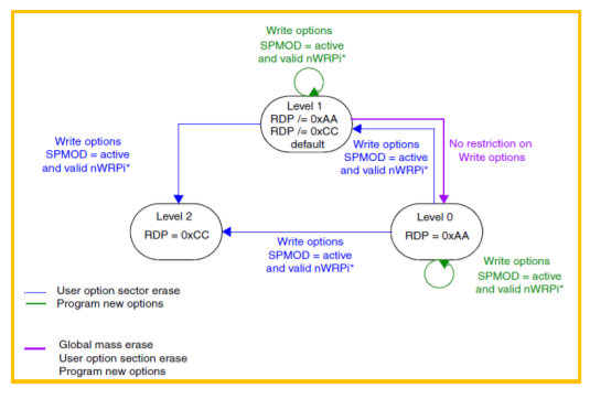
PCROP 保护等级设定如下:

三. 如何使用 PCROP 功能
1. 需要使用 6.50 以上版本的 EWARM(IAR),使能 C/C++ Complier --> Code--> No data reads in code memory ;
![}T03QT${}$UBKH%G]9IQ.png](data/attachment/forum/202202/27/161406uoymfudddtudyudu.png "}T03QT${}$UBKH%G]9IQ.png")
2. 修改 stm32f4xx_flash.icf 文件,定义 PCROP 保护的地址空间;

本文使用 STM32F429NIH6 芯片的 0x08008000---0x0800BFFF(Sector 2)作为 PCROP 保护区域,stm32f4xx_flash.icf 修改如下:
- /*###ICF### Section handled by ICF editor, don't touch! ****/
- /*-Editor annotation file-*/
- /* IcfEditorFile="$TOOLKIT_DIR$\config\ide\IcfEditor\cortex_v1_0.xml" */
- /*-Specials-*/
- define symbol __ICFEDIT_intvec_start__ = 0x08000000;
- /*-Memory Regions-*/
- define symbol __ICFEDIT_region_ROM_start__ = 0x08000000;
- define symbol __ICFEDIT_region_ROM_end__ = 0x08003FFF;
- define symbol __ICFEDIT_region_CODE_start__ = 0x08008000;
- define symbol __ICFEDIT_region_CODE_end__ = 0x0800BFFF;
- define symbol __ICFEDIT_region_RAM_start__ = 0x20000000;
- define symbol __ICFEDIT_region_RAM_end__ = 0x2002FFFF;
- define symbol __ICFEDIT_region_CCMRAM_start__ = 0x10000000;
- define symbol __ICFEDIT_region_CCMRAM_end__ = 0x1000FFFF;
- /*-Sizes-*/
- define symbol __ICFEDIT_size_cstack__ = 0x400;
- define symbol __ICFEDIT_size_heap__ = 0x200;
- /**** End of ICF editor section. ###ICF###*/
- define memory mem with size = 4G;
- define region ROM_region = mem:[from __ICFEDIT_region_ROM_start__ to
- __ICFEDIT_region_ROM_end__];
- define region CODE_region = mem:[from __ICFEDIT_region_CODE_start__ to
- __ICFEDIT_region_CODE_end__];
- define region RAM_region = mem:[from __ICFEDIT_region_RAM_start__ to
- __ICFEDIT_region_RAM_end__];
- define region CCMRAM_region = mem:[from __ICFEDIT_region_CCMRAM_start__ to
- __ICFEDIT_region_CCMRAM_end__];
- define region TabCode = [from 0x08004000 to 0x08007FFF];
- place in TabCode { ro section .tab, };
- define block CSTACK with alignment = 8, size = __ICFEDIT_size_cstack__ { };
- define block HEAP with alignment = 8, size = __ICFEDIT_size_heap__ { };
- initialize by copy { readwrite };
- do not initialize { section .noinit };
- place at address mem:__ICFEDIT_intvec_start__ { readonly section .intvec };
- place in CODE_region {section .CODE_Flash};
- place in ROM_region { readonly };
- place in RAM_region { readwrite,
- block CSTACK, block HEAP };
3. 修改 startup file (.s)文件 Reset_Handler 中 LDR 修改为 BLX:
- Reset_Handler
- LDR R0, =SystemInit
- BLX R0
- LDR R0, =__iar_program_start
- BX R0
- 修改为:
- Reset_Handler
- BLX SystemInit
- BLX __iar_program_start
4. 定义程序到 PCROP 保护区域中:
本文实例文件 Sector_Test.c 中定义 Light_Togger()函数定义在 0x08008000-0x0800BFFF 区域:
- #include "stm32f4xx.h"
- #pragma location = ".CODE_Flash"
- void Light_Toggle(void)
- {
- GPIOG->BSRRH = GPIO_Pin_6 | GPIO_Pin_7;
- }
5. 使用 STVP 对 OPTION BYTE 进行编程,使能 PCROP,并且选择保护区域:

此时可以读取下 0x08008000---0x0800BFFF 区域的数据,可以看到改 PCROP 空间数据不可读,但程序依然可以调用该区域函数---- Light_Togger()
![]RUOY[W~QY~O_D}SPG1)IPD.png](data/attachment/forum/202202/27/161406rjtzooontvcejddv.png "]RUOY[W~QY~O_D}SPG1)IPD.png")
四.本文所用测试代码说明以及代码
Main 函数作为客户程序代码,而需要调用的函数 Light_Togger()位于 PCROP 保护区域(0x08008000---0x0800BFFF),实现 GPIOG_6/GPIOG_7 端口的 Toggle;
Main.c 文件如下:
- /* Includes ------------------------------------------------------------------*/
- #include "main.h"
- extern void Light_Toggle(void);
- int main(void)
- {
- unsigned int i;
- GPIO_InitTypeDef GPIO_InitStructure;
- /* GPIOG Peripheral clock enable */
- RCC_AHB1PeriphClockCmd(RCC_AHB1Periph_GPIOG, ENABLE);
- /* Configure PG6 and PG8 in output pushpull mode */
- GPIO_InitStructure.GPIO_Pin = GPIO_Pin_6 | GPIO_Pin_7;
- GPIO_InitStructure.GPIO_Mode = GPIO_Mode_OUT;
- GPIO_InitStructure.GPIO_OType = GPIO_OType_PP;
- GPIO_InitStructure.GPIO_Speed = GPIO_Speed_100MHz;
- GPIO_InitStructure.GPIO_PuPd = GPIO_PuPd_NOPULL;
- GPIO_Init(GPIOG, &GPIO_InitStructure);
- while(1)
- {
- GPIOG->BSRRL = GPIO_Pin_6 | GPIO_Pin_7;
- i = 0xFFFFFF;
- while(i--);
- Light_Toggle();
- i = 0xFFFFFF;
- while(i--);
- }
- }
Sector_Test.c 如下:
- #include "stm32f4xx.h"
- #pragma location = ".CODE_Flash"
- void Light_Toggle(void)
- {
- GPIOG->BSRRH = GPIO_Pin_6 | GPIO_Pin_7;
- }
|
.png) STMCU小助手
发布时间:2022-2-27 16:13
STMCU小助手
发布时间:2022-2-27 16:13
 微信公众号
微信公众号
 手机版
手机版