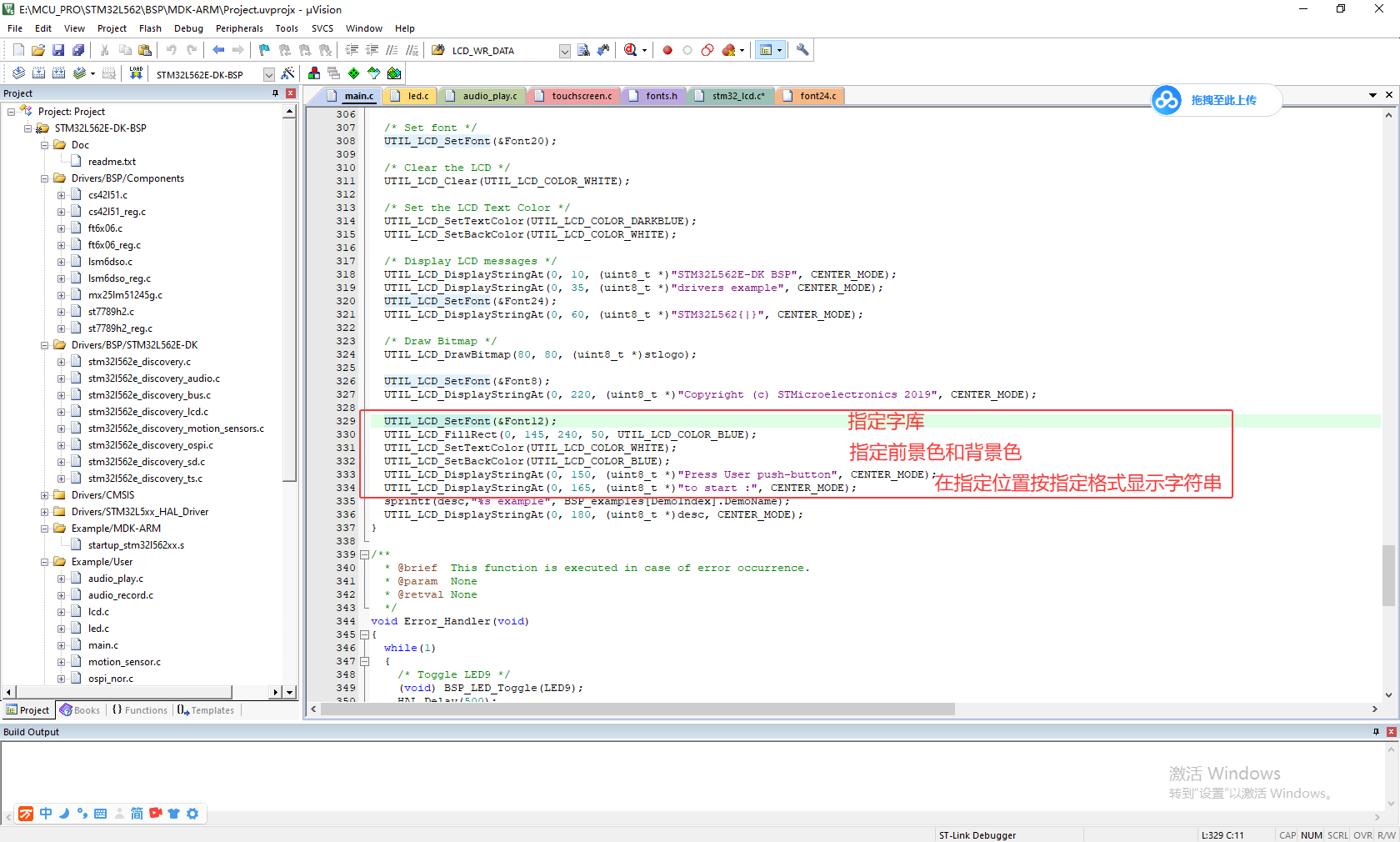



官方例程中显示不同大小的字符都是共用一个函数,即先指定字库、前景色和背景色,然后再将字符串及起始行列、对齐方式作为参数传送给字符串显示函数UTIL_LCD_DisplayStringAt(),如下图所示:/ T+ ` b! f! t& E' m4 s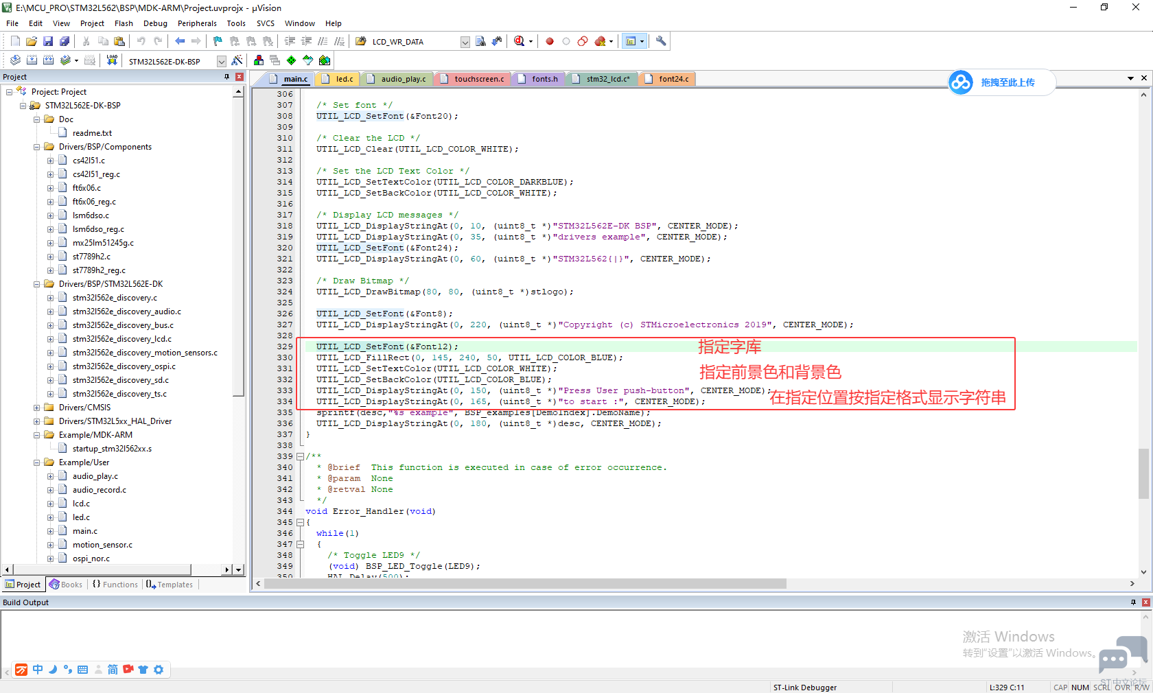
: D( {3 p$ w- Y6 P, c2 I8 f 在UTIL_LCD_DisplayStringAt()函数中也仅仅是处理好显示的起始位置后,依次将字符串逐个字符传递给后续函数UTIL_LCD_DisplayChar(refcolumn, Ypos, *Text)处理: 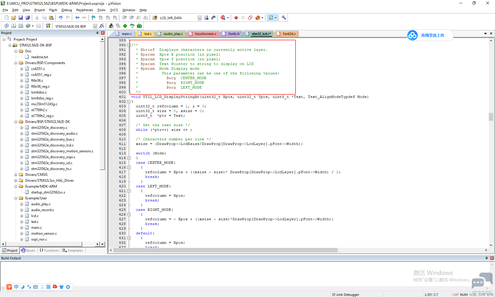
' U* f: O4 f( \" |7 |+ L2 } 后续的DisplayChar()函数如下: $ E0 m1 X& T* j% } /** * @brief Displays one character in currently active layer.在当前活动层中显示一个字符。. g9 U( C, ~" f! V3 j * @param Xpos Start column address * @param Ypos Line where to display the character shape.+ s9 U, U5 N h * @param Ascii Character ascii code0 m& }. e3 o% ?6 b * This parameter must be a number between Min_Data = 0x20 and Max_Data = 0x7E( D0 }& g) c( O8 X3 T: b */ void UTIL_LCD_DisplayChar(uint32_t Xpos, uint32_t Ypos, uint8_t Ascii) { DrawChar(Xpos, Ypos, &DrawProp[DrawProp->LcdLayer].pFont->table[(Ascii-' ') *\ DrawProp[DrawProp->LcdLayer].pFont->Height * ((DrawProp[DrawProp->LcdLayer].pFont->Width + 7) / 8)]);5 g: J9 H1 a& [! {2 ?' g }& A+ w4 r/ {5 o$ t+ _0 K9 d 在这个函数中也只是将之前指定的字库设置好,继续交给DrawChar()函数执行,DrawChar函数如下:- C6 Z3 |0 k4 A, D, b4 f1 B3 Z3 `8 X . P5 o. n7 [' D: t# `2 g1 ^+ G( S o /** * @brief Draws a character on LCD.! u7 q$ K3 R% W& L, ~) A' ~ * @param Xpos Line where to display the character shape * @param Ypos Start column address: Z5 `1 ~: t* G z& O6 } * @param pData Pointer to the character data! d" K$ V3 N, c. r' S! H *// C4 U; y2 h. g. A% C" i: n- Q static void DrawChar(uint32_t Xpos, uint32_t Ypos, const uint8_t *pData)3 G# [" i- G, X B5 e+ {: v { uint32_t i = 0, j = 0, offset;& u" c3 @1 i7 o% ] uint32_t height, width; uint8_t *pchar;% T1 S _1 w: v& c s5 r uint32_t line; 6 N) [$ U- I% _ Y; T% c height = DrawProp[DrawProp->LcdLayer].pFont->Height; width = DrawProp[DrawProp->LcdLayer].pFont->Width; uint16_t rgb565[24];0 L& w7 D% g1 ]1 |" G6 z, D uint32_t argb8888[24];% ]0 z! `# B( z offset = 8 *((width + 7)/8) - width ;/ ?- q5 y; `1 a1 _7 C- A for(i = 0; i < height; i++) {/ n N. ]* B) \ pchar = ((uint8_t *)pData + (width + 7)/8 * i); switch(((width + 7)/8)) J7 f8 W1 u2 E, I O {( w3 z l2 V2 z. _, c ' C9 ^- P4 ?/ y" ^4 g case 1: line = pchar[0];8 s& F/ y$ Y/ o+ X8 W break; case 2:2 i8 w# W1 r/ I0 @: e: P" h5 d line = (pchar[0]<< 8) | pchar[1]; ?! N$ c8 U/ }$ p! u0 ~* f3 J; b: ] break; 5 _* V* y5 m, D case 3:( L8 q( [4 b C, [5 \6 y" j default: line = (pchar[0]<< 16) | (pchar[1]<< 8) | pchar[2]; break; }7 z3 x( C8 g! l! l. \ if(DrawProp[DrawProp->LcdLayer].LcdPixelFormat == LCD_PIXEL_FORMAT_RGB565)0 ]! ]: {2 J9 m& W8 Y: v { for (j = 0; j < width; j++) {+ e8 a7 y' l7 [4 t- q if(line & (1 << (width- j + offset- 1)))- ?2 T! S6 w1 s {# q, Z' r( @8 C# f3 [1 ` rgb565[j] = CONVERTARGB88882RGB565(DrawProp[DrawProp->LcdLayer].TextColor); } else; A! O' G ^3 k; V9 X { rgb565[j] = CONVERTARGB88882RGB565(DrawProp[DrawProp->LcdLayer].BackColor);6 `0 ]0 B9 x% @9 B } } UTIL_LCD_FillRGBRect(Xpos, Ypos++, (uint8_t*)&rgb565[0], width, 1); }) J2 P2 ]6 A# l, J, { else {% i( m2 G5 i2 ?. ^" N, H for (j = 0; j < width; j++)& e- @$ {2 _6 H& y3 x' a { if(line & (1 << (width- j + offset- 1))) {9 C' I s- Z4 \3 B( G! I argb8888[j] = DrawProp[DrawProp->LcdLayer].TextColor; }: |3 h% u: Z" o1 g* C" \# W else; H+ N, b! W* l! H6 I1 |" u0 C1 X( F {+ I, b/ `: a+ _& x7 I9 ` argb8888[j] = DrawProp[DrawProp->LcdLayer].BackColor; }5 u- i* F% |) a7 ?1 G, |/ z } UTIL_LCD_FillRGBRect(Xpos, Ypos++, (uint8_t*)&argb8888[0], width, 1); } } }) k' S4 N$ V" j# _: _# ?) R 3 D9 o2 N) v$ O 在这个函数中,将字库中的字模逐个点交给写矩形的函数,在屏幕中“画”出字符来。 我好奇的是:为什么不使用画点的函数UTIL_LCD_SetPixel(),而使用画矩形的函数UTIL_LCD_FillRGBRect()? - k5 L! t* Y- h" e |
STM32C543RC开发板Stop、Sleep和standby模式测试
【STM32C5教程】(10)LPUART DMA 通信实验
【STM32C5教程】(9)DAC 模拟量信号输出实验
【STM32C5教程】(8)ADC 模拟量数据采集实验
【STM32C5教程】(7)TIM1 互补 PWM 输出实验
【STM32C5教程】(6)定时器 PWM 输出实验
【STM32C5教程】(5)定时器周期中断实验
【STM32C5教程】(4)GPIO 外部中断实验
【STM32C5教程】(3)GPIO 按键输入实验
STM32C542RC开发板PWM呼吸灯及多功能按键实验
 微信公众号
微信公众号
 手机版
手机版