|
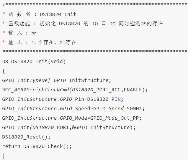
本实验所要实现的功能是:系统开启时首先检测 DS18B20 温度传感器是否存在,若存在输出相应的提示信息,然后间隔 500ms 读取一次 DS18B20 的温度,并通过串口打印输出,最后让 D1 指示灯不断闪烁,提示系统正常运行。程序框架如下: (1)初始化 DS18B20 (2)编写读取温度函数 (3)编写主函数 因为 DS18B20 是单总线通信,所以需要使用 STM32F1 的 PG11 管脚模拟单总线时序,单总线相关时序在前面已经介绍。下面我们打开“DS18B20 温度传感器实验”工程,在 APP 工程组中添加ds18b20.c 文件(里面包含了 DS18B20 驱动程序),同时还要包含对应的头文件路径。 要使用 PG11 管脚模拟单总线时序,就必须使能端口时钟及初始化 GPIO。初始化代码如下: - /****************************************************************
- * 函 数 名 : DS18B20_Init
- * 函数功能 : 初始化 DS18B20 的 IO 口 DQ 同时检测DS的存在
- * 输 入 : 无
- * 输 出 : 1:不存在,0:存在
- *****************************************************************/
- u8 DS18B20_Init(void)
- {
- GPIO_InitTypeDef GPIO_InitStructure;
- RCC_APB2PeriphClockCmd(DS18B20_PORT_RCC,ENABLE);
- GPIO_InitStructure.GPIO_Pin=DS18B20_PIN;
- GPIO_InitStructure.GPIO_Speed=GPIO_Speed_50MHz;
- GPIO_InitStructure.GPIO_Mode=GPIO_Mode_Out_PP;
- GPIO_Init(DS18B20_PORT,&GPIO_InitStructure);
- DS18B20_Reset();
- return DS18B20_Check();
- }
该函数带有一个返回值,如果返回值为 1 表示 DS18B20 初始化失败,返回值为 0表示初始化成功。函数返回值其实就是通过调用 DS18B20_Check函数获得,此函数用来检测DS18B20是否存在。初始化函数内还调用了DS18B20_Reset函数,这两个函数其实就是根据前面介绍的初始化时序编写,对应的代码如下: - /****************************************************************
- * 函 数 名 : DS18B20_Reset
- * 函数功能 : 复位 DS18B20
- * 输 入 : 无
- * 输 出 : 无
- *****************************************************************/
- void DS18B20_Reset(void)
- {
- DS18B20_IO_OUT(); //SET PG11 OUTPUT
- DS18B20_DQ_OUT=0; //拉低 DQ
- delay_us(750); //拉低 750us
- DS18B20_DQ_OUT=1; //DQ=1
- delay_us(15); //15US
- }
- /****************************************************************
- * 函 数 名 : DS18B20_Check
- * 函数功能 : 检测 DS18B20 是否存在
- * 输 入 : 无
- * 输 出 : 1:未检测到 DS18B20 的存在,0:存在
- *****************************************************************/
- u8 DS18B20_Check(void)
- {
- u8 retry=0;
- DS18B20_IO_IN();//SET PG11 INPUT
- while (DS18B20_DQ_IN&&retry<200)
- {
- retry++;
- delay_us(1);
- };
- if(retry>=200)return 1;
- else retry=0;
- while (!DS18B20_DQ_IN&&retry<240)
- {
- retry++;
- delay_us(1);
- };
- if(retry>=240)return 1;
- return 0;
- }
由于采用单总线,所以数据的写入和读取都是在 PG11 引脚上完成,所以当写入数据的时候需要配置此引脚为输出模式, 当读取数据的时候需要配置此引脚为输入模式,因此会有以下两个函数: - /****************************************************************
- * 函 数 名 : DS18B20_IO_IN
- * 函数功能 : DS18B20_IO 输入配置
- * 输 入 : 无
- * 输 出 : 无
- *****************************************************************/
- void DS18B20_IO_IN(void)
- {
- GPIO_InitTypeDef GPIO_InitStructure;
- GPIO_InitStructure.GPIO_Pin=DS18B20_PIN;
- GPIO_InitStructure.GPIO_Mode=GPIO_Mode_IPU;
- GPIO_Init(DS18B20_PORT,&GPIO_InitStructure);
- }
- /****************************************************************
- * 函 数 名 : DS18B20_IO_OUT
- * 函数功能 : DS18B20_IO 输出配置
- * 输 入 : 无
- * 输 出 : 无
- *****************************************************************/
- void DS18B20_IO_OUT(void)
- {
- GPIO_InitTypeDef GPIO_InitStructure;
- GPIO_InitStructure.GPIO_Pin=DS18B20_PIN;
- GPIO_InitStructure.GPIO_Speed=GPIO_Speed_50MHz;
- GPIO_InitStructure.GPIO_Mode=GPIO_Mode_Out_PP;
- GPIO_Init(DS18B20_PORT,&GPIO_InitStructure);
- }
其实也可以直接使用寄存器来配置管脚的模式,可参考 GPIO寄存器部分。
| .png) STMCU小助手
发布时间:2022-6-27 18:00
STMCU小助手
发布时间:2022-6-27 18:00
 微信公众号
微信公众号
 手机版
手机版