一、实验前期准备
本次实验的 MCU 是 STM32F103C8T6 芯片,通过 SPI 通信实现 W25Q128 的读写操作。
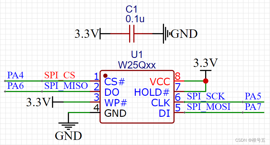
1. 原理图

2. 引脚连接

二、SPI 底层驱动
SPI.c
- #include "SPI.h"
- /*
- SPI引脚初始化配置
- **PA4------CS
- **PA5------SCLK
- **PA6------MISO
- **PA7------MOSI
- */
- static void SPI1_GPIO_Config(void)
- {
- GPIO_InitTypeDef GPIO_InitStructure;
-
- RCC_APB2PeriphClockCmd( RCC_APB2Periph_GPIOA, ENABLE );//PORTA时钟使能
- GPIO_InitStructure.GPIO_Pin = GPIO_Pin_5| GPIO_Pin_6|GPIO_Pin_7;
- GPIO_InitStructure.GPIO_Mode = GPIO_Mode_AF_PP; //PA5/6/7复用推挽输出
- GPIO_InitStructure.GPIO_Speed = GPIO_Speed_50MHz;
- GPIO_Init(GPIOA, &GPIO_InitStructure); //初始化GPIOA
-
- GPIO_InitStructure.GPIO_Pin = GPIO_Pin_4;
- GPIO_InitStructure.GPIO_Mode = GPIO_Mode_Out_PP; //PA4推挽输出
- GPIO_InitStructure.GPIO_Speed = GPIO_Speed_50MHz;
- GPIO_Init(GPIOA, &GPIO_InitStructure); //初始化GPIOA
- GPIO_SetBits(GPIOA,GPIO_Pin_4|GPIO_Pin_5|GPIO_Pin_6|GPIO_Pin_7); //初始上拉输出
- }
- //SPI1初始化函数
- void SPI1_Init(void)
- {
- SPI1_GPIO_Config();//SPI引脚初始化配置
- SPI_InitTypeDef SPI_InitStructure;
-
- RCC_APB2PeriphClockCmd( RCC_APB2Periph_SPI1, ENABLE );//SPI1时钟使能
-
- SPI_InitStructure.SPI_Direction = SPI_Direction_2Lines_FullDuplex; //设置SPI单向或者双向的数据模式:SPI设置为双线双向全双工
- SPI_InitStructure.SPI_Mode = SPI_Mode_Master; //设置SPI工作模式:设置为主SPI
- SPI_InitStructure.SPI_DataSize = SPI_DataSize_8b; //设置SPI的数据大小:SPI发送接收8位帧结构
- SPI_InitStructure.SPI_CPOL = SPI_CPOL_High; //串行同步时钟的空闲状态为高电平
- SPI_InitStructure.SPI_CPHA = SPI_CPHA_2Edge; //串行同步时钟的第二个跳变沿(上升或下降)数据被采样
- SPI_InitStructure.SPI_NSS = SPI_NSS_Soft; //NSS信号由硬件(NSS管脚)还是软件(使用SSI位)管理:内部NSS信号有SSI位控制
- SPI_InitStructure.SPI_BaudRatePrescaler = SPI_BaudRatePrescaler_256; //定义波特率预分频的值:波特率预分频值为256
- SPI_InitStructure.SPI_FirstBit = SPI_FirstBit_MSB; //指定数据传输从MSB位还是LSB位开始:数据传输从MSB位开始
- SPI_InitStructure.SPI_CRCPolynomial = 7; //CRC值计算的多项式
- SPI_Init(SPI1, &SPI_InitStructure); //根据SPI_InitStruct中指定的参数初始化外设SPIx寄存器
-
- SPI_Cmd(SPI1, ENABLE); //使能SPI外设
- SPI1_ReadWriteByte(0xFF);//启动传输
- }
- /*
- SPI的读写操作
- **TxData:要写入的字节
- **返回值:读取到的字节
- */
- uint8_t SPI1_ReadWriteByte(uint8_t TxData)
- {
- while (SPI_I2S_GetFlagStatus(SPI1, SPI_I2S_FLAG_TXE) == RESET) //检查指定的SPI标志位设置与否:发送缓存空标志位
- {
- //等待发送完成
- }
- SPI_I2S_SendData(SPI1, TxData); //通过外设SPIx发送一个数据
- while (SPI_I2S_GetFlagStatus(SPI1, SPI_I2S_FLAG_RXNE) == RESET) //检查指定的SPI标志位设置与否:接受缓存非空标志位
- {
- //等待接收完成
- }
- return SPI_I2S_ReceiveData(SPI1); //返回通过SPIx最近接收的数据
- }
SPI.h
- #ifndef __SPI_H
- #define __SPI_H
- #include "stm32f10x.h"
- #define SPI_CS(a) if (a) \
- GPIO_SetBits(GPIOA,GPIO_Pin_4);\
- else \
- GPIO_ResetBits(GPIOA,GPIO_Pin_4)
- void SPI1_Init(void);//SPI1初始化函数
- uint8_t SPI1_ReadWriteByte(uint8_t TxData);//SPI1读写函数
- #endif
三、读取 W25Q128 设备 ID
本次实验是:读取 W25Q128 设备 ID,然后通过串口1打印出来。
通过简单的实验来调试,有利于发现问题。
通过W25Q128的数据手册可知其设备ID如下图所示:

W25Q128.c
- #include "W25Q128.h"
- #include "SPI.h"
- uint8_t W25Q128_ReadWriteByte(uint8_t TxData)//函数包装一下
- {
- return SPI1_ReadWriteByte(TxData);
- }
- uint16_t W25Q128_ReadID(void)//读取芯片ID
- {
- uint16_t Temp = 0;
- W25Q128_CS(0);
- W25Q128_ReadWriteByte(W25X_ManufactDeviceID);//发送读取ID命令
- W25Q128_ReadWriteByte(0x00);
- W25Q128_ReadWriteByte(0x00);
- W25Q128_ReadWriteByte(0x00);
- Temp|=W25Q128_ReadWriteByte(0xFF)<<8;
- Temp|=W25Q128_ReadWriteByte(0xFF);
- W25Q128_CS(1);
- return Temp;
- }
W25Q128.h
- #ifndef __W25Q128_H
- #define __W25Q128_H
- #include "stm32f10x.h"
- //操作指令表
- #define W25X_ManufactDeviceID 0x90 //制造商+设备ID
- #define W25Q128_CS(a) SPI_CS(a)
- uint8_t W25Q128_ReadWriteByte(uint8_t TxData);//函数包装一下
- uint16_t W25Q128_ReadID(void);//读取芯片ID
- #endif
main.c
- #include <stdio.h>
- #include "Uart1.h"
- #include "delay.h"
- #include "SPI.h"
- #include "W25Q128.h"
- uint16_t W25Q128_ID=0;
- int main (void)
- {
- Uart1_init();
- SPI1_Init();
-
- W25Q128_ID = W25Q128_ReadID();
- while(1)
- {
- printf("\nW25Q128_ID=0x%X\n",W25Q128_ID);
- delay_ms(500);
- }
- }
实验结果

接收到 W25Q128 设备ID 为0xEF17
四、读写 W25Q128 外部 Flash
W25Q128.c
- #include "W25Q128.h"
- #include "SPI.h"
- uint8_t W25Q128_ReadWriteByte(uint8_t TxData)//函数包装一下
- {
- return SPI1_ReadWriteByte(TxData);
- }
- uint16_t W25Q128_ReadID(void)//读取芯片ID
- {
- uint16_t Temp = 0;
- W25Q128_CS(0);
- W25Q128_ReadWriteByte(W25X_ManufactDeviceID);//发送读取ID命令
- W25Q128_ReadWriteByte(0x00);
- W25Q128_ReadWriteByte(0x00);
- W25Q128_ReadWriteByte(0x00);
- Temp|=W25Q128_ReadWriteByte(0xFF)<<8;
- Temp|=W25Q128_ReadWriteByte(0xFF);
- W25Q128_CS(1);
- return Temp;
- }
- //读取W25Q128的状态寄存器
- //BIT7 6 5 4 3 2 1 0
- //SPR RV TB BP2 BP1 BP0 WEL BUSY
- //SPR:默认0,状态寄存器保护位,配合WP使用
- //TB,BP2,BP1,BP0:FLASH区域写保护设置
- //WEL:写使能锁定
- //BUSY:忙标记位(1,忙;0,空闲)
- //默认:0x00
- uint8_t W25Q128_ReadSR(void)//读取状态寄存器
- {
- uint8_t byte=0;
- W25Q128_CS(0); //使能器件
- W25Q128_ReadWriteByte(W25X_ReadStatusReg1); //发送读取状态寄存器命令
- byte=W25Q128_ReadWriteByte(0Xff); //读取一个字节
- W25Q128_CS(1); //取消片选
- return byte;
- }
- //写W25Q128状态寄存器
- //只有SPR,TB,BP2,BP1,BP0(bit 7,5,4,3,2)可以写!!!
- void W25Q128_WriteSR(uint8_t sr)//写状态寄存器
- {
- W25Q128_CS(0); //使能器件
- W25Q128_ReadWriteByte(W25X_WriteStatusReg1); //发送写取状态寄存器命令
- W25Q128_ReadWriteByte(sr); //写入一个字节
- W25Q128_CS(1); //取消片选
- }
- void W25Q128_Write_Enable(void) //写使能
- {
- W25Q128_CS(0);
- W25Q128_ReadWriteByte(W25X_WriteEnable);
- W25Q128_CS(1);
- }
- void W25Q128_Write_Disable(void) //禁止写入
- {
- W25Q128_CS(0);
- W25Q128_ReadWriteByte(W25X_WriteDisable);
- W25Q128_CS(1);
- }
- void W25Q128_Read(uint8_t* pBuffer,uint32_t ReadAddr,uint16_t NumByteToRead)
- {
- W25Q128_CS(0); //使能器件
- W25Q128_ReadWriteByte(W25X_ReadData); //发送读取命令
- W25Q128_ReadWriteByte((uint8_t)((ReadAddr)>>16)); //发送24bit地址
- W25Q128_ReadWriteByte((uint8_t)((ReadAddr)>>8));
- W25Q128_ReadWriteByte((uint8_t)ReadAddr);
- for(uint16_t i=0;i<NumByteToRead;i++)
- {
- pBuffer<i>=W25Q128_ReadWriteByte(0XFF); //循环读数
- }
- W25Q128_CS(1);
- }
- void W25Q128_Write_Page(uint8_t* pBuffer,uint32_t WriteAddr,uint16_t NumByteToWrite)
- {
- W25Q128_Write_Enable(); //SET WEL
- W25Q128_CS(0); //使能器件
- W25Q128_ReadWriteByte(W25X_PageProgram); //发送写页命令
- W25Q128_ReadWriteByte((uint8_t)((WriteAddr)>>16)); //发送24bit地址
- W25Q128_ReadWriteByte((uint8_t)((WriteAddr)>>8));
- W25Q128_ReadWriteByte((uint8_t)WriteAddr);
- for(uint16_t i=0;i<NumByteToWrite;i++)
- {
- W25Q128_ReadWriteByte(pBuffer<i>);//循环写数
- }
- W25Q128_CS(1); //取消片选
- W25Q128_Wait_Busy(); //等待写入结束
- }
- //无检验写SPI FLASH
- //必须确保所写的地址范围内的数据全部为0XFF,否则在非0XFF处写入的数据将失败!
- //具有自动换页功能
- void W25Q128_Write_NoCheck(uint8_t* pBuffer,uint32_t WriteAddr,uint16_t NumByteToWrite)
- {
- uint16_t pageremain=256-WriteAddr%256; //单页剩余的字节数
- if(NumByteToWrite<=pageremain)pageremain=NumByteToWrite;//不大于256个字节
- while(1)
- {
- W25Q128_Write_Page(pBuffer,WriteAddr,pageremain);
- if(NumByteToWrite==pageremain) break;//写入结束了
- else
- {
- pBuffer+=pageremain;
- WriteAddr+=pageremain;
- NumByteToWrite-=pageremain; //减去已经写入了的字节数
- if(NumByteToWrite>256)pageremain=256; //一次可以写入256个字节
- else pageremain=NumByteToWrite; //不够256个字节了
- }
- }
- }
- //写SPI FLASH
- //在指定地址开始写入指定长度的数据
- //该函数带擦除操作!
- //pBuffer:数据存储区
- //WriteAddr:开始写入的地址(24bit)
- //NumByteToWrite:要写入的字节数(最大65535)
- uint8_t W25Q128_BUFFER[4096];
- void W25Q128_Write(uint8_t* pBuffer,uint32_t WriteAddr,uint16_t NumByteToWrite)
- {
- uint16_t i;
- uint8_t * W25Q128_BUF;
- W25Q128_BUF=W25Q128_BUFFER;
- uint32_t secpos = WriteAddr/4096;//扇区地址
- uint16_t secoff = WriteAddr%4096;//在扇区内的偏移
- uint16_t secremain = 4096-secoff;//扇区剩余空间大小
- if(NumByteToWrite<=secremain) secremain=NumByteToWrite;//不大于4096个字节
- while(1)
- {
- W25Q128_Read(W25Q128_BUF,secpos*4096,4096);//读出整个扇区的内容
- for(i=0;i<secremain;i++)//校验数据
- {
- if(W25Q128_BUF[secoff+i]!=0XFF) break;//需要擦除
- }
- if(i<secremain)//需要擦除
- {
- W25Q128_Erase_Sector(secpos*4096);//擦除这个扇区
- for(i=0;i<secremain;i++) //复制
- {
- W25Q128_BUF[i+secoff]=pBuffer<i>;
- }
- W25Q128_Write_NoCheck(W25Q128_BUF,secpos*4096,4096);//写入整个扇区
- }else W25Q128_Write_NoCheck(pBuffer,WriteAddr,secremain);//写已经擦除了的,直接写入扇区剩余区间.
- if(NumByteToWrite==secremain) break;//写入结束了
- else//写入未结束
- {
- secpos++;//扇区地址增1
- secoff=0;//偏移位置为0
- pBuffer+=secremain; //指针偏移
- WriteAddr+=secremain;//写地址偏移
- NumByteToWrite-=secremain; //字节数递减
- if(NumByteToWrite>4096) secremain=4096; //下一个扇区还是写不完
- else secremain=NumByteToWrite; //下一个扇区可以写完了
- }
- }
- }
- //擦除一个扇区
- //Dst_Addr:扇区地址 根据实际容量设置
- //擦除一个扇区的最少时间:150ms
- void W25Q128_Erase_Sector(uint32_t Dst_Addr)
- {
- W25Q128_Write_Enable(); //SET WEL
- W25Q128_Wait_Busy();
- W25Q128_CS(0); //使能器件
- W25Q128_ReadWriteByte(W25X_SectorErase); //发送扇区擦除指令
- W25Q128_ReadWriteByte((uint8_t)((Dst_Addr)>>16)); //发送24bit地址
- W25Q128_ReadWriteByte((uint8_t)((Dst_Addr)>>8));
- W25Q128_ReadWriteByte((uint8_t)Dst_Addr);
- W25Q128_CS(1); //取消片选
- W25Q128_Wait_Busy(); //等待擦除完成
- }
- //擦除整个芯片
- //等待时间超长...
- void W25Q128_Erase_Chip(void)
- {
- W25Q128_Write_Enable(); //SET WEL
- W25Q128_Wait_Busy();
- W25Q128_CS(0); //使能器件
- W25Q128_ReadWriteByte(W25X_ChipErase); //发送片擦除命令
- W25Q128_CS(1); //取消片选
- W25Q128_Wait_Busy(); //等待芯片擦除结束
- }
- //等待空闲
- void W25Q128_Wait_Busy(void)
- {
- while((W25Q128_ReadSR()&0x01)==0x01); // 等待BUSY位清空
- }
- //进入掉电模式
- void W25Q128_PowerDown(void)
- {
- W25Q128_CS(0); //使能器件
- W25Q128_ReadWriteByte(W25X_PowerDown); //发送掉电命令
- W25Q128_CS(1); //取消片选
- }
- //掉电唤醒
- void W25Q128_WAKEUP(void)
- {
- W25Q128_CS(0); //使能器件
- W25Q128_ReadWriteByte(W25X_ReleasePowerDown);
- W25Q128_CS(1); //取消片选
- } </i></i></i>
W25Q128.h
#ifndef __W25Q128_H
#define __W25Q128_H
#include "stm32f10x.h"
//操作指令表
#define W25X_WriteEnable 0x06 //写使能
#define W25X_WriteDisable 0x04 //写禁止
#define W25X_ReadStatusReg1 0x05 //读状态寄存器1
#define W25X_ReadStatusReg2 0x35 //读状态寄存器2
#define W25X_ReadStatusReg3 0x15 //读状态寄存器3
#define W25X_WriteStatusReg1 0x01 //写状态寄存器1
#define W25X_WriteStatusReg2 0x31 //写状态寄存器2
#define W25X_WriteStatusReg3 0x11 //写状态寄存器3
#define W25X_ReadData 0x03 //读数据
#define W25X_FastReadData 0x0B //快读
#define W25X_FastReadDual 0x3B //双输出快读
#define W25X_PageProgram 0x02 //页编程
#define W25X_BlockErase 0xD8 //块擦除(64K)
#define W25X_SectorErase 0x20 //扇区擦除(4K)
#define W25X_ChipErase 0xC7 //芯片擦除
#define W25X_PowerDown 0xB9 //掉电
#define W25X_ReleasePowerDown 0xAB //释放掉电
#define W25X_DeviceID 0xAB //器件ID
#define W25X_ManufactDeviceID 0x90 //制造商+设备ID
#define W25X_JedecDeviceID 0x9F //电子元件ID
#define W25Q128_CS(a) SPI_CS(a)
uint8_t W25Q128_ReadWriteByte(uint8_t TxData);//函数包装一下
uint16_t W25Q128_ReadID(void);//读取芯片ID
uint8_t W25Q128_ReadSR(void);//读取状态寄存器
void W25Q128_WriteSR(uint8_t sr);//写状态寄存器
void W25Q128_Write_Enable(void);//写使能
void W25Q128_Write_Disable(void);//禁止写入
void W25Q128_Read(uint8_t* pBuffer,uint32_t ReadAddr,uint16_t NumByteToRead); //读取数据
void W25Q128_Write_Page(uint8_t* pBuffer,uint32_t WriteAddr,uint16_t NumByteToWrite);//页写
void W25Q128_Write_NoCheck(uint8_t* pBuffer,uint32_t WriteAddr,uint16_t NumByteToWrite);//无检验写数据,可自动翻页
void W25Q128_Write(uint8_t* pBuffer,uint32_t WriteAddr,uint16_t NumByteToWrite);//写入数据,带擦写功能
void W25Q128_Erase_Sector(uint32_t Dst_Addr);//擦除扇区
void W25Q128_Erase_Chip(void);//擦除整个芯片
void W25Q128_Wait_Busy(void);//等待空闲
void W25Q128_PowerDown(void); //进入掉电模式
void W25Q128_WAKEUP(void);//掉电唤醒
#endif
1
2
3
4
5
6
7
8
9
10
11
12
13
14
15
16
17
18
19
20
21
22
23
24
25
26
27
28
29
30
31
32
33
34
35
36
37
38
39
40
41
42
43
44
45
46
47
48
49
50
51
52
53
54
main.c
#include <stdio.h>
#include "Uart1.h"
#include "delay.h"
#include "SPI.h"
#include "W25Q128.h"
uint16_t W25Q128_ID=0;
uint8_t Write_data[20]={1,2,3,4,5,6,7,8,9,10,11,12,13,14,15,16,17,18,19,20};
uint8_t Read_data[100];
int main (void)
{
Uart1_init();
SPI1_Init();
W25Q128_ID=W25Q128_ReadID();
W25Q128_Write_Page(Write_data,0x01,20);
while(1)
{
W25Q128_Read(Read_data,0x00,100);
for(int i=0;i<100;i++)
{
printf(" 0x%X ",Read_data);
}
printf("\nW25Q128_ID=0x%X\n",W25Q128_ID);
delay_ms(500);
}
}
1
2
3
4
5
6
7
8
9
10
11
12
13
14
15
16
17
18
19
20
21
22
23
24
25
26
27
28
29
实验结果
————————————————
版权声明:根号五
|
.png) STMCU小助手
发布时间:2022-9-6 21:44
STMCU小助手
发布时间:2022-9-6 21:44

 微信公众号
微信公众号
 手机版
手机版