1.CubeMx的配置步骤
修改上一次IC捕获的ioc文件来生成工程

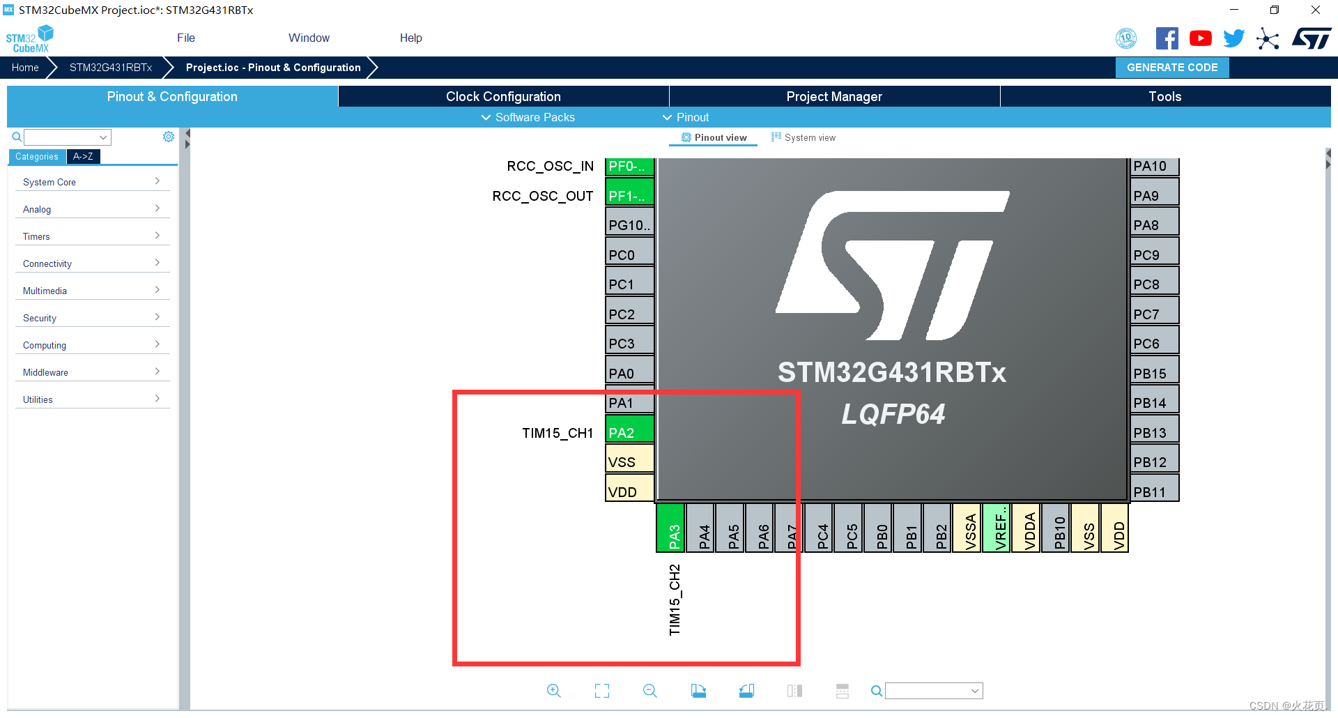
修改PA2,PA3为定时器15的通道1和通道2。


2.生成工程
点击GENERATE CODE生成代码后点击Open Project即可。

3.测试代码
interrupt.h:- #ifndef __INTERRUPT_H__
- #define __INTERRUPT_H__
- #include "main.h"
- void HAL_TIM_IC_CaptureCallback(TIM_HandleTypeDef *htim);
- void HAL_TIM_OC_DelayElapsedCallback(TIM_HandleTypeDef *htim);
- #endif
interrupt.c:
- #include "interrupt.h"
- #include "lcd.h"
- #include "stdio.h"
- unsigned int Period = 0;
- unsigned int HighTime = 0;
- unsigned char OC1_Duty = 25;
- unsigned char OC2_Duty = 75;
- unsigned short OC1_Pulse = 1000;
- unsigned short OC2_Pulse = 4000;
- void HAL_TIM_IC_CaptureCallback(TIM_HandleTypeDef *htim)
- {
- if(htim->Instance == TIM2)
- {
- if(htim->Channel == HAL_TIM_ACTIVE_CHANNEL_1)
- {
- Period = HAL_TIM_ReadCapturedValue(htim, TIM_CHANNEL_1); //读取直接通道
- HighTime = HAL_TIM_ReadCapturedValue(htim, TIM_CHANNEL_2); //读取间接通道
- __HAL_TIM_SetCounter(htim, 0);
- HAL_TIM_IC_Start_IT(htim, TIM_CHANNEL_1); //开启中断以便于下次采值
- HAL_TIM_IC_Start_IT(htim, TIM_CHANNEL_2);
- }
- }
- }
- void HAL_TIM_OC_DelayElapsedCallback(TIM_HandleTypeDef *htim)
- {
- if(htim->Instance == TIM15)
- {
- unsigned short CapVal = 0;
- if(htim->Channel == HAL_TIM_ACTIVE_CHANNEL_1)
- {
- CapVal = __HAL_TIM_GetCompare(htim, TIM_CHANNEL_1);
- if(HAL_GPIO_ReadPin(GPIOA, GPIO_PIN_2) == GPIO_PIN_RESET)
- {
- __HAL_TIM_SET_COMPARE(htim, TIM_CHANNEL_1, CapVal + OC1_Pulse - OC1_Duty / 100.0 * OC1_Pulse);
- }
- else
- {
- __HAL_TIM_SET_COMPARE(htim, TIM_CHANNEL_1, CapVal + OC1_Duty / 100.0 * OC1_Pulse);
- }
-
- }
- else if(htim->Channel == HAL_TIM_ACTIVE_CHANNEL_2)
- {
- CapVal = __HAL_TIM_GetCompare(htim, TIM_CHANNEL_2);
- if(HAL_GPIO_ReadPin(GPIOA, GPIO_PIN_3) == GPIO_PIN_RESET)
- {
- __HAL_TIM_SetCompare(htim, TIM_CHANNEL_2, CapVal + (1 - OC2_Duty / 100.0) * OC2_Pulse);
- }
- else
- {
- __HAL_TIM_SetCompare(htim, TIM_CHANNEL_2, CapVal + OC2_Duty / 100.0 * OC2_Pulse);
- }
- }
- }
- }
main.c:
- /* USER CODE BEGIN Header */
- /**
- ******************************************************************************
- * @file : main.c
- * @brief : Main program body
- ******************************************************************************
- * @attention
- *
- * <h2><center>© Copyright (c) 2023 STMicroelectronics.
- * All rights reserved.</center></h2>
- *
- * This software component is licensed by ST under BSD 3-Clause license,
- * the "License"; You may not use this file except in compliance with the
- * License. You may obtain a copy of the License at:
- * opensource.org/licenses/BSD-3-Clause
- *
- ******************************************************************************
- */
- /* USER CODE END Header */
- /* Includes ------------------------------------------------------------------*/
- #include "main.h"
- #include "tim.h"
- #include "gpio.h"
- /* Private includes ----------------------------------------------------------*/
- /* USER CODE BEGIN Includes */
- #include "lcd.h"
- #include "stdio.h"
- /* USER CODE END Includes */
- /* Private typedef -----------------------------------------------------------*/
- /* USER CODE BEGIN PTD */
- /* USER CODE END PTD */
- /* Private define ------------------------------------------------------------*/
- /* USER CODE BEGIN PD */
- /* USER CODE END PD */
- /* Private macro -------------------------------------------------------------*/
- /* USER CODE BEGIN PM */
- /* USER CODE END PM */
- /* Private variables ---------------------------------------------------------*/
- /* USER CODE BEGIN PV */
- extern unsigned int Period;
- extern unsigned int HighTime;
- char text[30];
- /* USER CODE END PV */
- /* Private function prototypes -----------------------------------------------*/
- void SystemClock_Config(void);
- /* USER CODE BEGIN PFP */
- /* USER CODE END PFP */
- /* Private user code ---------------------------------------------------------*/
- /* USER CODE BEGIN 0 */
- /* USER CODE END 0 */
- /**
- * @brief The application entry point.
- * @retval int
- */
- int main(void)
- {
- /* USER CODE BEGIN 1 */
- /* USER CODE END 1 */
- /* MCU Configuration--------------------------------------------------------*/
- /* Reset of all peripherals, Initializes the Flash interface and the Systick. */
- HAL_Init();
- /* USER CODE BEGIN Init */
- /* USER CODE END Init */
- /* Configure the system clock */
- SystemClock_Config();
- /* USER CODE BEGIN SysInit */
- /* USER CODE END SysInit */
- /* Initialize all configured peripherals */
- MX_GPIO_Init();
- MX_TIM2_Init();
- MX_TIM15_Init();
- MX_TIM3_Init();
- /* USER CODE BEGIN 2 */
- HAL_TIM_IC_Start_IT(&htim2, TIM_CHANNEL_1);
- HAL_TIM_IC_Start_IT(&htim2, TIM_CHANNEL_2);
- HAL_TIM_OC_Start_IT(&htim15, TIM_CHANNEL_1);
- HAL_TIM_OC_Start_IT(&htim15, TIM_CHANNEL_2);
- LCD_Init();
- LCD_Clear(Black);
- LCD_SetBackColor(Black);
- LCD_SetTextColor(White);
- /* USER CODE END 2 */
- /* Infinite loop */
- /* USER CODE BEGIN WHILE */
- while (1)
- {
- /* USER CODE END WHILE */
- /* USER CODE BEGIN 3 */
- sprintf(text, "frq:%.2f ", 1000000.0 / Period); //分频成1MHz所以这里1000000.0作为被除数
- LCD_DisplayStringLine(Line0, text);
- sprintf(text, "Duty:%.2f ", HighTime / (float)Period * 100); //占空比为高电平时间 / 周期 * 100%
- LCD_DisplayStringLine(Line1, text);
- }
- /* USER CODE END 3 */
- }
- /**
- * @brief System Clock Configuration
- * @retval None
- */
- void SystemClock_Config(void)
- {
- RCC_OscInitTypeDef RCC_OscInitStruct = {0};
- RCC_ClkInitTypeDef RCC_ClkInitStruct = {0};
- /** Configure the main internal regulator output voltage
- */
- HAL_PWREx_ControlVoltageScaling(PWR_REGULATOR_VOLTAGE_SCALE1);
- /** Initializes the RCC Oscillators according to the specified parameters
- * in the RCC_OscInitTypeDef structure.
- */
- RCC_OscInitStruct.OscillatorType = RCC_OSCILLATORTYPE_HSE;
- RCC_OscInitStruct.HSEState = RCC_HSE_ON;
- RCC_OscInitStruct.PLL.PLLState = RCC_PLL_ON;
- RCC_OscInitStruct.PLL.PLLSource = RCC_PLLSOURCE_HSE;
- RCC_OscInitStruct.PLL.PLLM = RCC_PLLM_DIV3;
- RCC_OscInitStruct.PLL.PLLN = 20;
- RCC_OscInitStruct.PLL.PLLP = RCC_PLLP_DIV2;
- RCC_OscInitStruct.PLL.PLLQ = RCC_PLLQ_DIV2;
- RCC_OscInitStruct.PLL.PLLR = RCC_PLLR_DIV2;
- if (HAL_RCC_OscConfig(&RCC_OscInitStruct) != HAL_OK)
- {
- Error_Handler();
- }
- /** Initializes the CPU, AHB and APB buses clocks
- */
- RCC_ClkInitStruct.ClockType = RCC_CLOCKTYPE_HCLK|RCC_CLOCKTYPE_SYSCLK
- |RCC_CLOCKTYPE_PCLK1|RCC_CLOCKTYPE_PCLK2;
- RCC_ClkInitStruct.SYSCLKSource = RCC_SYSCLKSOURCE_PLLCLK;
- RCC_ClkInitStruct.AHBCLKDivider = RCC_SYSCLK_DIV1;
- RCC_ClkInitStruct.APB1CLKDivider = RCC_HCLK_DIV1;
- RCC_ClkInitStruct.APB2CLKDivider = RCC_HCLK_DIV1;
- if (HAL_RCC_ClockConfig(&RCC_ClkInitStruct, FLASH_LATENCY_2) != HAL_OK)
- {
- Error_Handler();
- }
- }
- /* USER CODE BEGIN 4 */
- /* USER CODE END 4 */
- /**
- * @brief This function is executed in case of error occurrence.
- * @retval None
- */
- void Error_Handler(void)
- {
- /* USER CODE BEGIN Error_Handler_Debug */
- /* User can add his own implementation to report the HAL error return state */
- __disable_irq();
- while (1)
- {
- }
- /* USER CODE END Error_Handler_Debug */
- }
- #ifdef USE_FULL_ASSERT
- /**
- * @brief Reports the name of the source file and the source line number
- * where the assert_param error has occurred.
- * @param file: pointer to the source file name
- * @param line: assert_param error line source number
- * @retval None
- */
- void assert_failed(uint8_t *file, uint32_t line)
- {
- /* USER CODE BEGIN 6 */
- /* User can add his own implementation to report the file name and line number,
- ex: printf("Wrong parameters value: file %s on line %d\r\n", file, line) */
- /* USER CODE END 6 */
- }
- #endif /* USE_FULL_ASSERT */
- /************************ (C) COPYRIGHT STMicroelectronics *****END OF FILE****/
4.演示效果

总结
从结果来看我们目标是PA2输出1000Hz占空比为25%的PWM波但最后测量频率为1026和23%的波形,误差比较大。PA3目标输出250Hz占空比为75%的PWM波,但最后输出的是252.84Hz和74.72%的PWM波,误差虽然存在但与PA2输出的波形比较,误差算是少一点,我们可以知道OC输出高频率PWM波时存在很严重的波形失真现象,但在输出低频率PWM波时这种情况就好一点,TIM的PWM模式不会有这样的问题但是PWM模式下定时器各个通道输出PWM波频率相同(占空比可以不同),不能实现每个通道占空比不同且频率也不同的情况。OC模式下虽然不支持输出高频率PWM波,但是它能实现每个通道的PWM波频率不同占空比也不同。
以上就是OC的配置过程,测试代码以及测试效果
————————————————
版权声明:火花页.
|
.png) STMCU小助手
发布时间:2023-3-1 20:55
STMCU小助手
发布时间:2023-3-1 20:55
 微信公众号
微信公众号
 手机版
手机版