【前言】
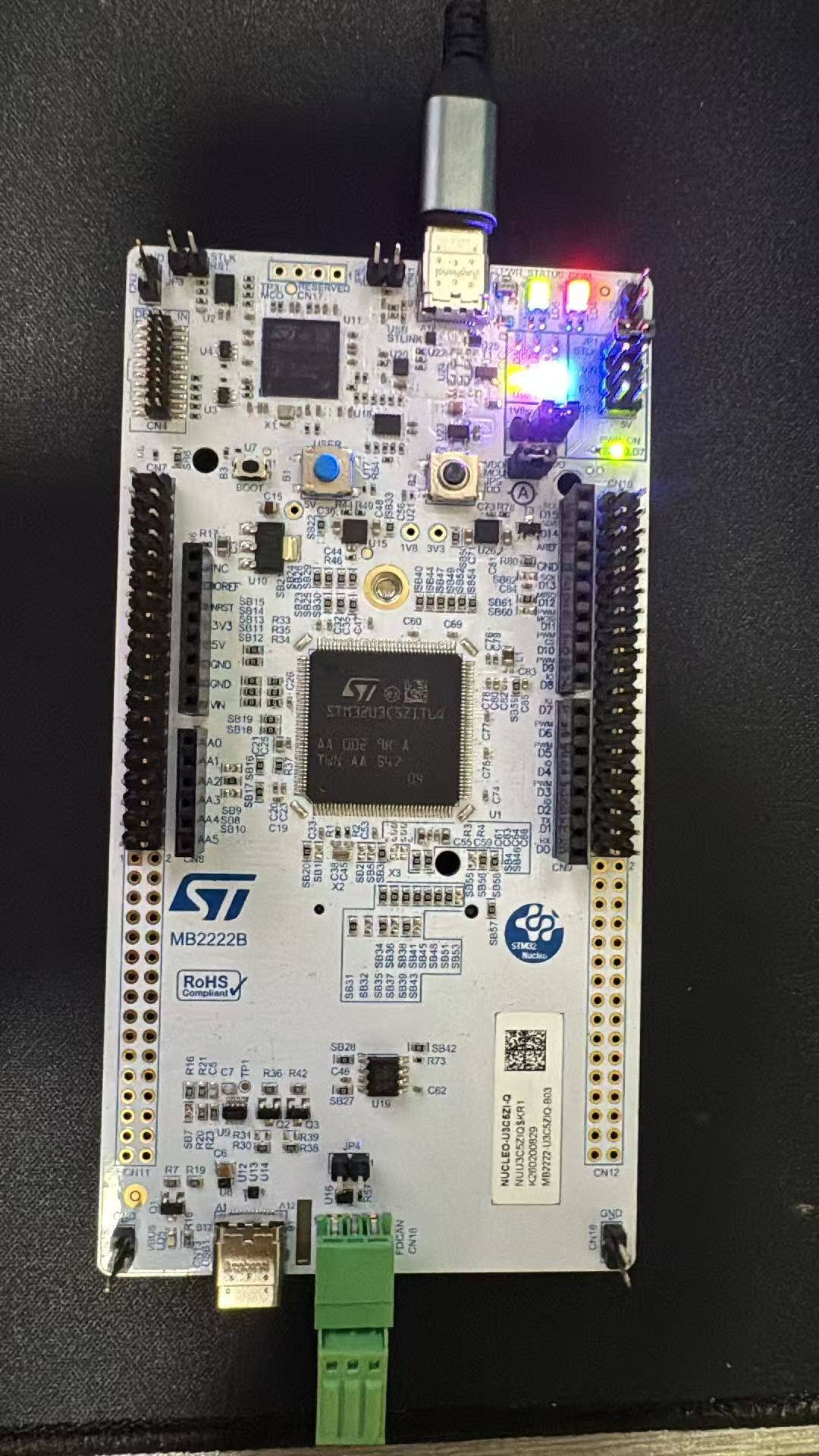
前面在使用stm32cubeide来创建st7789的驱动,需要自己写很多东西,但是使用zephyr就超级简单了。本篇将详细介绍如何操作。
【基础环境】
需要在wsl下面创建zephyr基础环境。
【工程创建】
在zephyrproject/app下面创建工程stm32u3c5_lcd
工程文件目录如下:
├── CMakeLists.txt
├── prj.conf
├── boards/
│   └── nucleo_u3c5zi_q.overlay   # device tree overlay
└── src/
└── main.c
1、首先创建prj.conf,需要打开gpio display st7789 等,源码如下:
CONFIG_GPIO=y
CONFIG_DISPLAY=y
CONFIG_ST7789V=y
CONFIG_VIDEO_DEVICE=y
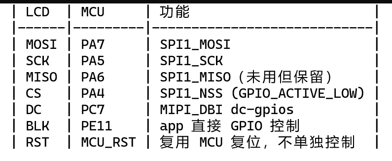
2、根据st7789接线,纺写ovley文件如下:
#include <zephyr/dt-bindings/display/panel.h>

/ {
    chosen {
        zephyr,display = &st7789v;
    };

    mipi_dbi {
        compatible = "zephyr,mipi-dbi-spi";
        spi-dev = <&spi1>;
        dc-gpios = <&gpioc 7 GPIO_ACTIVE_HIGH>;
        reset-gpios = <&gpiod 0 GPIO_ACTIVE_HIGH>;
        write-only;
        #address-cells = <1>;
        #size-cells = <0>;

        st7789v: st7789v@0 {
            compatible = "sitronix,st7789v";
            reg = <0>;
            mipi-max-frequency = <40000000>;

            width = <240>;
            height = <320>;
            x-offset = <0>;
            y-offset = <0>;

            vcom = <0x28>;
            gctrl = <0x35>;
            vrhs = <0x10>;
            vdvs = <0x20>;
            mdac = <0x00>;
            gamma = <0x01>;
            pixel-format = <PANEL_PIXEL_FORMAT_RGB_565>;
            lcm = <0x2c>;
            porch-param = [0c 0c 00 33 33];
            cmd2en-param = [5a 69 02 00];
            pwctrl1-param = [a4 a1];
            pvgam-param = [d0 00 02 07 0a 28 32 44 42 06 0e 12 14 17];
            nvgam-param = [d0 00 02 07 0a 28 31 54 47 0e 1c 17 1b 1e];
            ram-param = [00 f0];
            rgb-param = [40 02 14];
            mipi-mode = "MIPI_DBI_MODE_SPI_4WIRE";
        };
    };
};

&spi1 {
    pinctrl-0 = <&spi1_sck_pa5 &spi1_miso_pa6 &spi1_mosi_pa7>;
    pinctrl-names = "default";
    cs-gpios = <&gpioa 4 GPIO_ACTIVE_LOW>;
    status = "okay";
};
3、最后在Main.c中添加测试代码
#include <zephyr/device.h>
#include <zephyr/devicetree.h>
#include <zephyr/drivers/display.h>
#include <zephyr/drivers/gpio.h>
#include <zephyr/kernel.h>

#define LOG_LEVEL CONFIG_LOG_DEFAULT_LEVEL
#include <zephyr/logging/log.h>
LOG_MODULE_REGISTER(app);

/* BLK (backlight) on PE11 */
#define BLK_GPIO_NODE   DT_NODELABEL(gpioe)
#define BLK_PIN     11

int main(void)
{
    const struct device *display_dev;
    const struct device *blk_gpio;
    int ret;

    LOG_INF("STM32U3C5 ST7789V LCD demo");

    display_dev = DEVICE_DT_GET(DT_CHOSEN(zephyr_display));
    if (!device_is_ready(display_dev)) {
        LOG_ERR("Display device not ready");
        return 0;
    }

    blk_gpio = DEVICE_DT_GET(BLK_GPIO_NODE);
    if (!device_is_ready(blk_gpio)) {
        LOG_ERR("BLK GPIO not ready");
        return 0;
    }

    ret = gpio_pin_configure(blk_gpio, BLK_PIN, GPIO_OUTPUT_HIGH);
    if (ret < 0) {
        LOG_ERR("BLK pin config failed: %d", ret);
        return 0;
    }

    LOG_INF("Display ready, backlight enabled");

    /* Wake display */
    display_blanking_off(display_dev);

    /* RGB565 color definitions */
    const uint16_t colors[3] = { 0xF800, 0x07E0, 0x001F }; /* R, G, B */
    const char *names[3] = { "RED", "GREEN", "BLUE" };

    struct display_buffer_descriptor desc = {
        .buf_size = 240 * 2,
        .width = 240,
        .height = 1,
        .pitch = 240,
    };

    uint16_t row[240];

    while (1) {
        for (int c = 0; c < 3; c++) {
            for (int i = 0; i < 240; i++) {
                row[i] = colors[c];
            }
            for (int y = 0; y < 320; y++) {
                ret = display_write(display_dev, 0, y, &desc, row);
                if (ret < 0) {
                    LOG_ERR("display_write failed: %d", ret);
                }
            }
            LOG_INF("Displaying %s", names[c]);
            k_sleep(K_SECONDS(2));
        }

        /* Blink backlight */
        gpio_pin_set(blk_gpio, BLK_PIN, 0);
        k_sleep(K_SECONDS(1));
        gpio_pin_set(blk_gpio, BLK_PIN, 1);
        k_sleep(K_SECONDS(1));
    }

    return 0;
}
CmakeList常规的代码。
【接线】
【编译】
执行:west build --build-dir build -b nucleo_u3c5zi_q
【烧录】
使用stm32cubeprogrammer烧到开发板,即可实现点亮lcd屏。





 微信公众号
微信公众号
 手机版
手机版