在刚开始学习单片机的时候,一直以为程序启动后就直接进入到了main函数,但是随着学习的深入才发现,程序在进入main函数前其实还要干好多事情。现在就来分析一下,STM32系列单片机程序在进入main函数前都在干些什么?
2P2SXEM{4@MD@K.png")
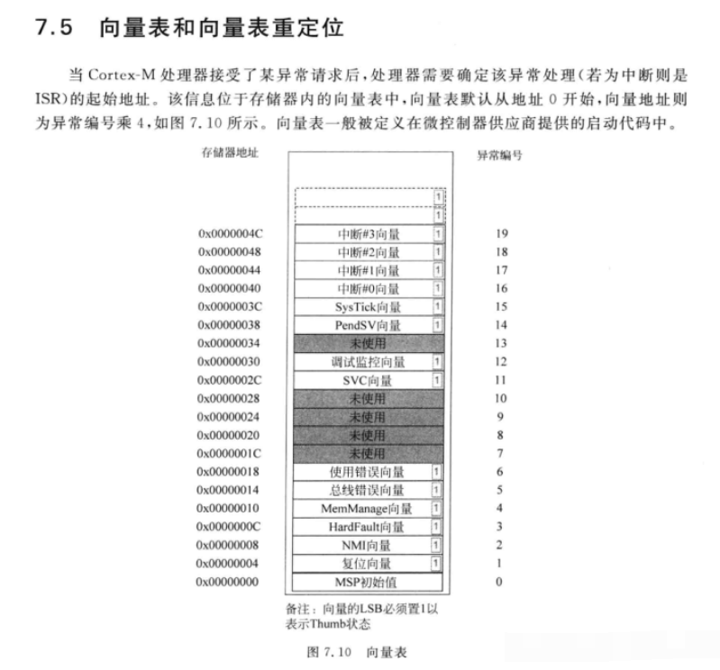
单片机上电后,程序首先跳转到地址0处,此时主堆栈指针MSP的初值也为0。然后单片机产生了复位信号,主堆栈指针加1,由于单片机内核为32位,所以地址增加一位,实际上是增加了32位,也就是增加了4个字节。此时MSP指针就指向了复位向量。而Cortex-M内核处理器的向量表可以重新定位,所以此时程序就会跳转到复位向量重新映射的地址处。
![_%3]EKZKPMAOD}WXWJBQI.png](data/attachment/forum/202203/20/211633cgyh0ap780p9z0fa.png "_%3]EKZKPMAOD}WXWJBQI.png")
![JMNH_KOQ~%[TAO`]QQPV9{W.png](data/attachment/forum/202203/20/211633jr2trp2svw4p3500.png "JMNH_KOQ~%[TAO`]QQPV9{W.png")
通过上面的两个图可以看到,通过复位向量的重映射后,MSP指针就会跳转到复位向量处,在STM32系列单片机中,复位向量的函数通常在启动文件startup_stm32f10x_xx.s中实现。
下来接着看一下复位函数都实现了哪些功能。
![1]CWCQQKY{~GC$I5_LXV(MR.png](data/attachment/forum/202203/20/211633dhgq5qzvwg5f3owg.png "1]CWCQQKY{~GC$I5_LXV(MR.png")
可以看到复位函数首先获取到了main()函数和系统初始化函数SystemInit()的地址,然后跳转到系统初始化函数中SystemInit()中,接着就会跳转到main函数中。
- void SystemInit ( void )
- {
- /* Reset the RCC clock configuration to the default reset state(for debug purpose) */
- /* Set HSION bit */
- RCC->CR |= ( uint32_t )0x00000001;
- /* Reset SW, HPRE, PPRE1, PPRE2, ADCPRE and MCO bits */
- #ifndef STM32F10X_CL
- RCC->CFGR &= ( uint32_t )0xF8FF0000;
- #else
- RCC->CFGR &= ( uint32_t )0xF0FF0000;
- #endif /* STM32F10X_CL */
- /* Reset HSEON, CSSON and PLLON bits */
- RCC->CR &= ( uint32_t )0xFEF6FFFF;
- /* Reset HSEBYP bit */
- RCC->CR &= ( uint32_t )0xFFFBFFFF;
- /* Reset PLLSRC, PLLXTPRE, PLLMUL and USBPRE/OTGFSPRE bits */
- RCC->CFGR &= ( uint32_t )0xFF80FFFF;
- #ifdef STM32F10X_CL
- /* Reset PLL2ON and PLL3ON bits */
- RCC->CR &= ( uint32_t )0xEBFFFFFF;
- /* Disable all interrupts and clear pending bits */
- RCC->CIR = 0x00FF0000;
- /* Reset CFGR2 register */
- RCC->CFGR2 = 0x00000000;
- #elif defined (STM32F10X_LD_VL) || defined (STM32F10X_MD_VL) || (defined STM32F10X_HD_VL)
- /* Disable all interrupts and clear pending bits */
- RCC->CIR = 0x009F0000;
- /* Reset CFGR2 register */
- RCC->CFGR2 = 0x00000000;
- #else
- /* Disable all interrupts and clear pending bits */
- RCC->CIR = 0x009F0000;
- #endif /* STM32F10X_CL */
- #if defined (STM32F10X_HD) || (defined STM32F10X_XL) || (defined STM32F10X_HD_VL)
- #ifdef DATA_IN_ExtSRAM
- SystemInit_ExtMemCtl();
- #endif /* DATA_IN_ExtSRAM */
- #endif
- /* Configure the System clock frequency, HCLK, PCLK2 and PCLK1 prescalers */
- /* Configure the Flash Latency cycles and enable prefetch buffer */
- SetSysClock();
- #ifdef VECT_TAB_SRAM
- SCB->VTOR = SRAM_BASE | VECT_TAB_OFFSET; /* Vector Table Relocation in Internal SRAM. */
- #else
- SCB->VTOR = FLASH_BASE | VECT_TAB_OFFSET; /* Vector Table Relocation in Internal FLASH. */
- #endif
- }
在系统复位函数SystemInit()中,主要是复位各个寄存器,将寄存器值设置位默认值,最后调用时钟设置函数 SetSysClock()对系统时钟进行设置。
- static void SetSysClock( void )
- {
- #ifdef SYSCLK_FREQ_HSE
- SetSysClockToHSE();
- #elif defined SYSCLK_FREQ_24MHz
- SetSysClockTo24();
- #elif defined SYSCLK_FREQ_36MHz
- SetSysClockTo36();
- #elif defined SYSCLK_FREQ_48MHz
- SetSysClockTo48();
- #elif defined SYSCLK_FREQ_56MHz
- SetSysClockTo56();
- #elif defined SYSCLK_FREQ_72MHz
- SetSysClockTo72();
- #endif
- /* If none of the define above is enabled, the HSI is used as System clock
- source (default after reset) */
- }
系统设置函数,根据不同的晶振和单片机型号,选择相应频率的时钟进行设置。
- static void SetSysClockTo72( void )
- {
- __IO uint32_t StartUpCounter = 0, HSEStatus = 0;
- /* SYSCLK, HCLK, PCLK2 and PCLK1 configuration ---------------------------*/
- /* Enable HSE */
- RCC->CR |= ( ( uint32_t )RCC_CR_HSEON );
- /* Wait till HSE is ready and if Time out is reached exit */
- do
- {
- HSEStatus = RCC->CR & RCC_CR_HSERDY;
- StartUpCounter++;
- }
- while( ( HSEStatus == 0 ) && ( StartUpCounter != HSE_STARTUP_TIMEOUT ) );
- if ( ( RCC->CR & RCC_CR_HSERDY ) != RESET )
- {
- HSEStatus = ( uint32_t )0x01;
- }
- else
- {
- HSEStatus = ( uint32_t )0x00;
- }
- if ( HSEStatus == ( uint32_t )0x01 )
- {
- /* Enable Prefetch Buffer */
- FLASH->ACR |= FLASH_ACR_PRFTBE;
- /* Flash 2 wait state */
- FLASH->ACR &= ( uint32_t )( ( uint32_t )~FLASH_ACR_LATENCY );
- FLASH->ACR |= ( uint32_t )FLASH_ACR_LATENCY_2;
- /* HCLK = SYSCLK */
- RCC->CFGR |= ( uint32_t )RCC_CFGR_HPRE_DIV1;
- /* PCLK2 = HCLK */
- RCC->CFGR |= ( uint32_t )RCC_CFGR_PPRE2_DIV1;
- /* PCLK1 = HCLK */
- RCC->CFGR |= ( uint32_t )RCC_CFGR_PPRE1_DIV2;
- #ifdef STM32F10X_CL
- /* Configure PLLs ------------------------------------------------------*/
- /* PLL2 configuration: PLL2CLK = (HSE / 5) * 8 = 40 MHz */
- /* PREDIV1 configuration: PREDIV1CLK = PLL2 / 5 = 8 MHz */
- RCC->CFGR2 &= ( uint32_t )~( RCC_CFGR2_PREDIV2 | RCC_CFGR2_PLL2MUL |
- RCC_CFGR2_PREDIV1 | RCC_CFGR2_PREDIV1SRC );
- RCC->CFGR2 |= ( uint32_t )( RCC_CFGR2_PREDIV2_DIV5 | RCC_CFGR2_PLL2MUL8 |
- RCC_CFGR2_PREDIV1SRC_PLL2 | RCC_CFGR2_PREDIV1_DIV5 );
- /* Enable PLL2 */
- RCC->CR |= RCC_CR_PLL2ON;
- /* Wait till PLL2 is ready */
- while( ( RCC->CR & RCC_CR_PLL2RDY ) == 0 )
- {
- }
- /* PLL configuration: PLLCLK = PREDIV1 * 9 = 72 MHz */
- RCC->CFGR &= ( uint32_t )~( RCC_CFGR_PLLXTPRE | RCC_CFGR_PLLSRC | RCC_CFGR_PLLMULL );
- RCC->CFGR |= ( uint32_t )( RCC_CFGR_PLLXTPRE_PREDIV1 | RCC_CFGR_PLLSRC_PREDIV1 |
- RCC_CFGR_PLLMULL9 );
- #else
- /* PLL configuration: PLLCLK = HSE * 9 = 72 MHz */
- RCC->CFGR &= ( uint32_t )( ( uint32_t )~( RCC_CFGR_PLLSRC | RCC_CFGR_PLLXTPRE |
- RCC_CFGR_PLLMULL ) );
- RCC->CFGR |= ( uint32_t )( RCC_CFGR_PLLSRC_HSE | RCC_CFGR_PLLMULL9 );
- #endif /* STM32F10X_CL */
- /* Enable PLL */
- RCC->CR |= RCC_CR_PLLON;
- /* Wait till PLL is ready */
- while( ( RCC->CR & RCC_CR_PLLRDY ) == 0 )
- {
- }
- /* Select PLL as system clock source */
- RCC->CFGR &= ( uint32_t )( ( uint32_t )~( RCC_CFGR_SW ) );
- RCC->CFGR |= ( uint32_t )RCC_CFGR_SW_PLL;
- /* Wait till PLL is used as system clock source */
- while ( ( RCC->CFGR & ( uint32_t )RCC_CFGR_SWS ) != ( uint32_t )0x08 )
- {
- }
- }
- else
- {
- /* If HSE fails to start-up, the application will have wrong clock
- configuration. User can add here some code to deal with this error */
- }
- }
- #endif
在系统时钟设置函数中,设置锁相环,及各个时钟的频率。
关于时钟的具体设置,可以参考下面这张图。
![W9ZU$~E9LX({OMI8O)X0]1Q.png](data/attachment/forum/202203/20/211634q2eydhdle1y112mu.png "W9ZU$~E9LX({OMI8O)X0]1Q.png")

通过上面的分析,可以知道,程序在进入main之前执行流程为
S7$RKYD4B.png")
这里大概分析了单片机在进入main函数之前,大概都做了哪些工作,对于具体的启动文件代码没做分析。对于启动文件startup_stm32f10x_hd.s的详细分析,在另一篇文章中进行说明。
|
.png) STMCU小助手
发布时间:2022-3-21 13:41
STMCU小助手
发布时间:2022-3-21 13:41
 微信公众号
微信公众号
 手机版
手机版