01. STM32F4串口简介
STM32F4 的串口资源相当丰富的,功能也相当强劲。ALIENTEK 探索者 STM32F4 开发板所使用的 STM32F407ZGT6 最多可提供 6 路串口,有分数波特率发生器、支持同步单线通信和半双工单线通讯、支持 LIN、支持调制解调器操作、智能卡协议和 IrDA SIR ENDEC 规范、具有 DMA 等。
02. 硬件设计
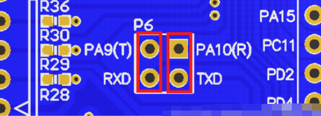
串口 1 与USB 串口并没有在 PCB上连接在一起,需要通过跳线帽来连接一下。这里我们把 P6 的 RXD 和 TXD 用跳线帽与 PA9 和 PA10 连接起来。
U06CQONVEH{N2.png")
03. 串口设置步骤
① 串口时钟使能,GPIO 时钟使能
② 设置引脚复用器映射
③ GPIO 端口初始化设置
④ 串口参数初始化
⑤ 初始化 NVIC 并且开启中断
⑥ 使能串口
串口时钟和GPIO时钟使能
- //使能GPIO时钟 PA9 PA10
- RCC_AHB1PeriphClockCmd(RCC_AHB1Periph_GPIOA, ENABLE);
- //使能USART时钟
- RCC_APB2PeriphClockCmd(RCC_APB2Periph_USART1, ENABLE);
设置引脚复用器映射- //设置GPIO复用
- GPIO_PinAFConfig(GPIOA, GPIO_PinSource9, GPIO_AF_USART1);
- GPIO_PinAFConfig(GPIOA, GPIO_PinSource10, GPIO_AF_USART1);
GPIO端口初始化
- //初始化GPIO
- GPIO_InitStruct.GPIO_Mode = GPIO_Mode_AF;
- GPIO_InitStruct.GPIO_Pin = GPIO_Pin_9 | GPIO_Pin_10;
- GPIO_InitStruct.GPIO_OType = GPIO_OType_PP;
- GPIO_InitStruct.GPIO_PuPd = GPIO_PuPd_UP;
- GPIO_InitStruct.GPIO_Speed = GPIO_Speed_50MHz;
-
- GPIO_Init(GPIOA, &GPIO_InitStruct);
串口初始化
- //串口初始化
- USART_InitStruct.USART_BaudRate = 115200;
- USART_InitStruct.USART_HardwareFlowControl = USART_HardwareFlowControl_None;
- USART_InitStruct.USART_Mode = USART_Mode_Rx | USART_Mode_Tx;
- USART_InitStruct.USART_Parity = USART_Parity_No;
- USART_InitStruct.USART_StopBits = USART_StopBits_1;
- USART_InitStruct.USART_WordLength = USART_WordLength_8b;
-
- USART_Init(USART1, &USART_InitStruct);
使能串口- //使能串口
- USART_Cmd(USART1, ENABLE);
数据发送- USART_SendData(USART1, 'A');
数据接收
- ch = USART_ReceiveData(USART1);
04. 程序示例一
通过串口发送数据
- #include "stm32f4xx.h"
- #include "delay.h"
- #include "led.h"
- #include "beep.h"
- #include "key.h"
- //Key0 控制LED1 Key1控制LED2
- int main(void)
- {
-
- GPIO_InitTypeDef GPIO_InitStruct;
-
- USART_InitTypeDef USART_InitStruct;
-
- //初始化
- delay_init(168);
- LED_Init();
- //使能GPIO时钟 PA9 PA10
- RCC_AHB1PeriphClockCmd(RCC_AHB1Periph_GPIOA, ENABLE);
-
- //使能USART时钟
- RCC_APB2PeriphClockCmd(RCC_APB2Periph_USART1, ENABLE);
- //设置GPIO复用
- GPIO_PinAFConfig(GPIOA, GPIO_PinSource9, GPIO_AF_USART1);
- GPIO_PinAFConfig(GPIOA, GPIO_PinSource10, GPIO_AF_USART1);
-
- //初始化GPIO
- GPIO_InitStruct.GPIO_Mode = GPIO_Mode_AF;
- GPIO_InitStruct.GPIO_Pin = GPIO_Pin_9 | GPIO_Pin_10;
- GPIO_InitStruct.GPIO_OType = GPIO_OType_PP;
- GPIO_InitStruct.GPIO_PuPd = GPIO_PuPd_UP;
- GPIO_InitStruct.GPIO_Speed = GPIO_Speed_50MHz;
-
- GPIO_Init(GPIOA, &GPIO_InitStruct);
-
- //串口初始化
- USART_InitStruct.USART_BaudRate = 115200;
- USART_InitStruct.USART_HardwareFlowControl = USART_HardwareFlowControl_None;
- USART_InitStruct.USART_Mode = USART_Mode_Rx | USART_Mode_Tx;
- USART_InitStruct.USART_Parity = USART_Parity_No;
- USART_InitStruct.USART_StopBits = USART_StopBits_1;
- USART_InitStruct.USART_WordLength = USART_WordLength_8b;
-
- USART_Init(USART1, &USART_InitStruct);
-
- //使能串口
- USART_Cmd(USART1, ENABLE);
-
- //数据发送
- while(1)
- {
- USART_SendData(USART1, 'A');
-
- delay_ms(1000);
- }
-
- }
05. 程序示例二
通过串口接收数据
- #include "stm32f4xx.h"
- #include "delay.h"
- #include "led.h"
- #include "beep.h"
- #include "key.h"
- //Key0 控制LED1 Key1控制LED2
- int main(void)
- {
- uint16_t ch;
-
- GPIO_InitTypeDef GPIO_InitStruct;
-
- USART_InitTypeDef USART_InitStruct;
-
- //初始化
- delay_init(168);
- LED_Init();
- //使能GPIO时钟 PA9 PA10
- RCC_AHB1PeriphClockCmd(RCC_AHB1Periph_GPIOA, ENABLE);
-
- //使能USART时钟
- RCC_APB2PeriphClockCmd(RCC_APB2Periph_USART1, ENABLE);
- //设置GPIO复用
- GPIO_PinAFConfig(GPIOA, GPIO_PinSource9, GPIO_AF_USART1);
- GPIO_PinAFConfig(GPIOA, GPIO_PinSource10, GPIO_AF_USART1);
-
- //初始化GPIO
- GPIO_InitStruct.GPIO_Mode = GPIO_Mode_AF;
- GPIO_InitStruct.GPIO_Pin = GPIO_Pin_9 | GPIO_Pin_10;
- GPIO_InitStruct.GPIO_OType = GPIO_OType_PP;
- GPIO_InitStruct.GPIO_PuPd = GPIO_PuPd_UP;
- GPIO_InitStruct.GPIO_Speed = GPIO_Speed_50MHz;
-
- GPIO_Init(GPIOA, &GPIO_InitStruct);
-
- //串口初始化
- USART_InitStruct.USART_BaudRate = 115200;
- USART_InitStruct.USART_HardwareFlowControl = USART_HardwareFlowControl_None;
- USART_InitStruct.USART_Mode = USART_Mode_Rx | USART_Mode_Tx;
- USART_InitStruct.USART_Parity = USART_Parity_No;
- USART_InitStruct.USART_StopBits = USART_StopBits_1;
- USART_InitStruct.USART_WordLength = USART_WordLength_8b;
-
- USART_Init(USART1, &USART_InitStruct);
-
- //使能串口
- USART_Cmd(USART1, ENABLE);
-
- //数据发送
- while(1)
- {
- ch = USART_ReceiveData(USART1);
- if (ch == '1')
- {
- LED1 = 1;
- LED2 = 1;
- }
- else if (ch == '0')
- {
- LED1 = 0;
- LED2 = 0;
- }
- }
-
- }
|
.png) STMCU小助手
发布时间:2022-4-2 21:00
STMCU小助手
发布时间:2022-4-2 21:00
 微信公众号
微信公众号
 手机版
手机版