1、概述
7 u% j' M7 G+ b4 E4 ~# L- |& C( z, t; a4 w! B% A0 f9 j
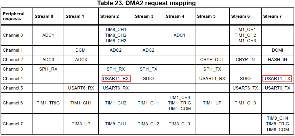
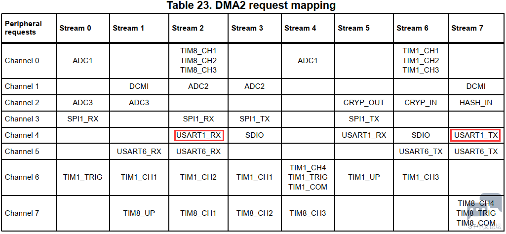
使用DMA发送数据,首先我们要确认使用的串口有没有DMA。& E6 d9 z, L: z& L
6 i+ s' y+ [# X6 ^: _
我们使用USART1串口外设,从数据手册中可以查到,USART1的发送和接收都是支持DMA的,使用的是DMA2.
# [& I0 h7 Z- K9 h
$ f3 z5 {* h8 [
 ! @. W% Z. W. _: q U9 L' w
. [! z8 D1 o8 G% a) n; y& t
接下来就是撸代码的时刻了 p/ }) O: y g+ }$ G
7 b- N/ \8 Q1 M- V r! G& o
02、代码) [6 ]5 M3 G- O) B
DMA串口发送的代码是在上一篇文章DMA串口接收的基础上修改的。
; W) j5 m' ? n& {% d$ t9 {$ N' b L d8 {
- void UART_Init(void)
. v/ T0 T; L5 t! j6 I - {
; @! E5 T" o8 m Q& w* t - USART_InitTypeDef USART_InitStructure;" g; |3 R/ a5 q5 L
- GPIO_InitTypeDef GPIO_InitStructure;0 y6 b7 x5 I; u+ [, V( p5 Z
- NVIC_InitTypeDef NVIC_InitStructure;) ?. T& L. ^. P* Q
3 T3 K2 Q& w% f* r0 C- /* Enable GPIO clock */, V. A; e8 Y( D3 H$ l
- RCC_AHB1PeriphClockCmd(RCC_AHB1Periph_GPIOA, ENABLE);; _% ^; U. W* Q! [$ u8 i; l
- /* Enable UART1 clock */# D1 O; y9 ]5 a3 i5 Q3 s
- RCC_APB2PeriphClockCmd(RCC_APB2Periph_USART1, ENABLE);
- \3 I+ h7 |* s) B2 f6 } - /* Connect PXx to USARTx_Tx*/' Q4 r% a8 _* {3 E) Q; `- F e5 R
- GPIO_PinAFConfig(GPIOA, 9, GPIO_AF_USART1);; _! q6 V! `+ w7 J$ J
- 4 d" e& {; Z5 L4 y, Z4 h
- /* Connect PXx to USARTx_Rx*/3 d' i, t- }* l$ O
- GPIO_PinAFConfig(GPIOA, 10, GPIO_AF_USART1);
, w' m- p" a0 e6 Q" r5 j# E; N- x ]
' e _8 n. v+ }6 I7 W- /* Configure USART Tx as alternate function *// e S: X+ e( W) W4 b
- GPIO_InitStructure.GPIO_OType = GPIO_OType_PP;
+ ^3 S! [6 N- b3 U) S - GPIO_InitStructure.GPIO_PuPd = GPIO_PuPd_UP;
4 c7 N3 r* A& ?! B: r7 K" ^ - GPIO_InitStructure.GPIO_Mode = GPIO_Mode_AF;& A7 f' H9 [5 E/ M: W" g' H
- 5 E2 L0 K3 @4 c% m& s y
- GPIO_InitStructure.GPIO_Pin = GPIO_Pin_9;& N, b' g. S! z F+ u" m/ I
- GPIO_InitStructure.GPIO_Speed = GPIO_Speed_50MHz;" C, r/ v. s M/ I8 ~3 D
- GPIO_Init(GPIOA, &GPIO_InitStructure);
' k; ?! N h; d# w/ V
5 U* {9 Q" {. b- /* Configure USART Rx as alternate function */
+ j3 D8 A' L% ~! ^' G - GPIO_InitStructure.GPIO_Mode = GPIO_Mode_AF;
/ R0 z% p0 y1 D - GPIO_InitStructure.GPIO_Pin = GPIO_Pin_10;! r$ C; q0 H% P* T+ k
- GPIO_Init(GPIOA, &GPIO_InitStructure);
- i, T8 m7 k/ y - 0 V1 V D: B* q. C% ?5 b2 d+ R
- USART_InitStructure.USART_BaudRate = 115200; J2 |, g' U2 u' A3 Q ^, h$ [
- USART_InitStructure.USART_WordLength = USART_WordLength_8b;
( O* a0 p* j0 m, s: D/ I - USART_InitStructure.USART_StopBits = USART_StopBits_1;
- O3 s- v3 }' V3 u0 J - USART_InitStructure.USART_Parity = USART_Parity_No;% R% d( F7 ~. s* a
- USART_InitStructure.USART_HardwareFlowControl = USART_HardwareFlowControl_None;/ T8 Y2 |3 M3 q
- USART_InitStructure.USART_Mode = USART_Mode_Rx | USART_Mode_Tx;, C, {; i9 {* c* L& h2 Y
- 8 h4 C S9 j- r0 Z! ` r" t
- /* USART configuration */- u8 m' Z' x0 `- V
- USART_Init(USART1, &USART_InitStructure);" m9 ~' E& ~7 |( c1 a0 S* m
3 R# x2 H$ B( e# _! L/ R d- USART_ITConfig(USART1, USART_IT_IDLE, ENABLE);
6 B$ o2 V6 Q; g) d3 p* o$ P v - 3 y: h6 _ D& U8 W0 J
- /* Enable the USARTx Interrupt */3 |- b9 |! w: R! U5 X. D- H& V3 Y
- NVIC_InitStructure.NVIC_IRQChannel = USART1_IRQn;) z& h8 A) F2 _
- NVIC_InitStructure.NVIC_IRQChannelPreemptionPriority =0;3 ~ X4 y6 B5 a7 ^" I
- NVIC_InitStructure.NVIC_IRQChannelSubPriority = 0;
0 z% R1 _/ |/ d: |4 y - NVIC_InitStructure.NVIC_IRQChannelCmd = ENABLE;+ o& ]) H' |4 U; p: J* N
- NVIC_Init(&NVIC_InitStructure);
9 Y( [/ J+ S5 S% B! }( Z% R% |
- | v9 v( } M, ]: Q! a9 h- /*使能串口DMA接收*/) z8 w* y8 Z. t; s
- USART_DMACmd(USART1, USART_DMAReq_Rx, ENABLE);5 k7 S& r z; B1 ?2 l
- /*使能串口DMA发送*/( A/ T/ a% G) p6 [0 M
- USART_DMACmd(USART1, USART_DMAReq_Tx, ENABLE);
/ }; d- L) m, I5 q2 r% T - : B' ~) M. r0 V
- /* Enable USART */
# L: C9 ?" [0 x6 A) G6 W$ D - USART_Cmd(USART1, ENABLE);, R( ^3 N7 V1 a) M, G- I
- }
$ I* p( W" N% M. f/ V( z
! P3 ^) u; C% p7 n在这里除了常规的串口配置,我们需要配置串口的DMA发送,和串口DMA接收一样的API函数,参数修改为USART_DMAReq_Tx即可。
]" Y& f2 M$ W0 G- l- p' ^* v" H7 g! i4 l) @5 w" m+ j( W5 ?
串口DMA发送配置: G g2 g1 l$ H2 W+ I b% W
8 I A* u: R6 d$ `
- void Uart_Send_DMA_Config(void)$ p- `9 J5 _2 W& \0 C2 e
- {0 ^9 k+ m" b& X. D
- DMA_InitTypeDef DMA_InitStructure;3 J$ e" d' O2 n# F
1 v% I! y0 i! r7 n3 l+ {2 q- /* Enable DMA clock */, Y9 x* Q, m+ I( U2 k
- RCC_AHB1PeriphClockCmd(RCC_AHB1Periph_DMA2, ENABLE);
& f1 {. c) E. Z. j - + r: c' ?) A0 m& ]- q4 p- o
- /* Reset DMA Stream registers (for debug purpose) */% y3 P8 X) `+ }9 _/ p0 }5 G2 a
- DMA_DeInit(DMA2_Stream7);9 X8 A' Z \' ~, a5 S: y* q
- ; U- g# x. r' H. U- H0 t
- /* Check if the DMA Stream is disabled before enabling it.3 }' @: i3 ?* r
- Note that this step is useful when the same Stream is used multiple times:% [ [; o Q9 i) _& m0 J( ?
- enabled, then disabled then re-enabled... In this case, the DMA Stream disable
3 I/ N6 W) h: r) a; U N - will be effective only at the end of the ongoing data transfer and it will
; N+ E# `" c( j* \ - not be possible to re-configure it before making sure that the Enable bit 2 w5 H4 U$ k& |' G1 `
- has been cleared by hardware. If the Stream is used only once, this step might
; t' o5 [, i& e& h6 J: m b - be bypassed. */
1 X6 Q0 q) W. P; m! B$ m, N - while (DMA_GetCmdStatus(DMA2_Stream7) != DISABLE)
( r. S: \) K% F: \" C( R; W - {
; e, @' C- u0 H* ~) r - }
- s$ j9 \3 o" N( S+ m. R1 n. ~. \ - ( C* O4 m5 q- G" C
- /* Configure DMA Stream */
5 {: f) |* b; p+ u7 V! a0 J - DMA_InitStructure.DMA_Channel = DMA_Channel_4; //DMA请求发出通道+ ^7 W6 d! o+ c% ]1 @
- DMA_InitStructure.DMA_PeripheralBaseAddr = (uint32_t)&USART1->DR;//配置外设地址
# `1 Q+ c8 I I) Z* w - DMA_InitStructure.DMA_Memory0BaseAddr = (uint32_t)UART_Buffer;//配置存储器地址
; M% b7 Y5 T! F1 q - DMA_InitStructure.DMA_DIR = DMA_DIR_MemoryToPeripheral;//传输方向配置
0 q; [; p" M8 F$ _; H0 k# x! V) X5 \- N - DMA_InitStructure.DMA_BufferSize = (uint32_t)UART_RX_LEN;//传输大小
- v' c. p1 t$ A3 n9 s - DMA_InitStructure.DMA_PeripheralInc = DMA_PeripheralInc_Disable;//外设地址不变
S. M2 {5 K2 I - DMA_InitStructure.DMA_MemoryInc = DMA_MemoryInc_Enable;//memory地址自增
2 r- k: y2 |" S2 f! i$ F - DMA_InitStructure.DMA_PeripheralDataSize = DMA_PeripheralDataSize_Byte;//外设地址数据单位/ o! y$ a% o; X4 ~9 S
- DMA_InitStructure.DMA_MemoryDataSize = DMA_MemoryDataSize_Byte;//memory地址数据单位7 @- F9 I' ]" Q
- DMA_InitStructure.DMA_Mode = DMA_Mode_Normal;//DMA模式:正常模式! d' B% g- a6 R Z. t. q0 ~
- DMA_InitStructure.DMA_Priority = DMA_Priority_High;//优先级:高
' P {. i( s6 H - DMA_InitStructure.DMA_FIFOMode = DMA_FIFOMode_Disable;//FIFO 模式不使能.
# Q( m0 J6 w# K" z - DMA_InitStructure.DMA_FIFOThreshold = DMA_FIFOThreshold_Full;// FIFO 阈值选择. j/ `! P# u& W3 W
- DMA_InitStructure.DMA_MemoryBurst = DMA_MemoryBurst_Single;//存储器突发模式选择,可选单次模式、 4 节拍的增量突发模式、 8 节拍的增量突发模式或 16 节拍的增量突发模式。! s5 V1 Q% _& w; e, o
- DMA_InitStructure.DMA_PeripheralBurst = DMA_PeripheralBurst_Single;//外设突发模式选择,可选单次模式、 4 节拍的增量突发模式、 8 节拍的增量突发模式或 16 节拍的增量突发模式。+ L- O" u) y. E4 ~
- DMA_Init(DMA2_Stream7, &DMA_InitStructure); " a' s9 X$ D2 q5 v e% l+ P7 w
% l: \9 \4 `' |1 x- /* DMA Stream enable */
! P% a7 W( ^7 c' ]+ o - // DMA_Cmd(DMA2_Stream7, ENABLE);
2 S- K3 W+ `$ n8 G" ^3 h) o - }
# \' t8 ^$ m: s* H1 G6 M! ^* E: m! f+ B1 {3 b
这里也是常规的DMA配置流程,不明白的同学请看文章《STM32DMA详解》,这里值得注意的是,配置完成并没有使能DMA2_Stream7,使能了就会立即将UART_Buffer的数据发送出去。- X, I* r8 F; _5 W% d
4 U6 [5 k+ R4 {; k) W/ ]6 l
其他代码处理4 r/ z4 `" Y$ U) f* p) N
1 R0 l) j; @2 C: g0 x- void USART1_IRQHandler(void)
8 o+ P8 r5 B+ O! } - {
+ g! v$ ~5 Y& f+ l - uint8_t temp;/ x1 g& E4 x! h3 O; d2 ^
- if(USART_GetFlagStatus(USART1, USART_FLAG_IDLE) == SET)
9 [+ p' t, h$ c- M - {
x7 V0 n( a4 h - DealWith_UartData();# `5 n8 t3 ~/ ~+ {9 l# @
- // USART_ClearFlag(USART1, USART_FLAG_IDLE);
% v h+ n2 {3 m' l u - temp = USART1->SR; " _' ]) z, f) q; Z
- temp = USART1->DR; //清USART_IT_IDLE标志
2 |" z( W0 E' k5 D - }" o5 w' H: z) ]8 m6 L. a
- }
6 E! s" P" I- S! K5 r- A
* M$ q" m+ a' \! Z" y; P$ S5 u- void DealWith_UartData()
6 R& c- q' E/ i* |5 ?; v - {
# c6 R2 ^( `* W/ h' f9 k/ f - DMA_Cmd(DMA2_Stream2, DISABLE);
4 X1 s" `9 b& T1 s5 F% w3 |5 D - UART_Receive_flg = 1;
+ ?8 r) b$ ]% D: I( f - UART_Receive_len = UART_RX_LEN - DMA_GetCurrDataCounter(DMA2_Stream2);
" y. y: c1 g+ i- Q# ]6 F - UART_Buffer[UART_Receive_len] = 0;& t4 m+ A& k( t! {
- DMA_SetCurrDataCounter(DMA2_Stream2,UART_RX_LEN); / c0 L8 U5 J( N
- DMA_ClearFlag(DMA2_Stream2, DMA_FLAG_TCIF2);
2 A% H$ F0 A a/ a, k; l - DMA_Cmd(DMA2_Stream2, ENABLE);( b6 `+ c' E( y' P, F0 \
- }7 O/ ]0 z1 A) G8 `# _4 P$ t3 _
- 4 F# B" N( O1 o- y! h( ^' s
- int main(void)
+ V7 N/ I) D5 p - {7 n/ o3 o0 |1 s0 x( a. F
- UART_Receive_flg = 0;4 z# ^# Q- {. O, \" u X' n
( e; _6 Z- x1 J+ y+ p3 ?$ M- Uart_Reveice_DMA_Config();- {/ L, I& u6 Y5 I3 u4 ^* ^
- Uart_Send_DMA_Config();# ^+ M. i N7 a, j& R
- UART_Init();2 ^7 c) `- K2 |
" L9 f5 {# h4 n& H5 h2 ?- while (1)5 \! ~" E$ g6 }3 q
- {6 Z/ i0 P" a+ n2 B8 d* w
- if(UART_Receive_flg)8 u0 y. z( t+ w N
- {
3 J$ \; w6 h6 E5 K - UART_Receive_flg = 0;
- P4 u; r* p- a - Uart_Send_DMA_Start();
2 ]6 T# M4 \6 J9 h( o+ u - }
' J Z* l. f' E: y - }. U' D7 K. G2 f% W. l
- }: @: s; z; K2 G% S# O/ v
5 T- o5 d- W7 s" V+ f3 x$ Q1 |2 D8 N上面3个函数,简单逻辑就是,当串口使用DMA接收了一定量的数据,就会通过串口DMA发送出去,串口DMA发送的代码如下:1 {3 _ n& g. K
1 d3 F4 o! l+ L( r- void Uart_Send_DMA_Start(void)
8 {3 v& U: A5 t' { - {) S+ T8 Y7 K) S# C5 W
- DMA_SetCurrDataCounter(DMA2_Stream7,UART_Receive_len);
/ v7 _) S, G! J' U0 e9 u( e, {/ J - DMA_ClearFlag(DMA2_Stream7, DMA_FLAG_TCIF7);
, N& g9 t @! X' s9 { - /* DMA Stream enable */* n1 p9 l3 r. c8 z
- DMA_Cmd(DMA2_Stream7, ENABLE);
6 o6 Q, i: w& I+ ^, t3 }1 |& h - }
03、后记' t! [' c. O- N/ ^3 ~
这一篇很简单,就是DMA使用的一个延伸,上面说了这么多,也贴了很多代码,不可能将所有代码全部贴出来,作为软件工程师,还是在IDE里看代码方便,如果感兴趣的话,可以到下面github链接下载代码,Keil和IAR的工程文件都有。
p" }( [" {! N- d" b* l4 J
5 P; Q5 _ i* [2 t
# L+ w' @6 H3 }8 c" y! L. o5 F/ H |





 STMCU小助手
发布时间:2022-4-16 21:00
 微信公众号
 手机版