首先,需要熟悉下一些重要的杂散的知识。

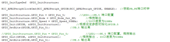
上图是一个标准的GPIO配置过程。
GPIO_InitTypeDef是一个结构体,


可以看出,CRL寄存器的每4位控制一个GPIO的工作状态。

上面的枚举类型设计得很巧妙,其用低四位代表具体输入/输出模式,低四位右移两位即是对应的寄存器配置,如下:
- (GPIO_Mode_AIN & 0X0F) >> 2 = 00B
- (GPIO_Mode_Out_PP & 0X0F) >> 2 = 00B
![JI8DXY_B]))3TWOV]51CFM1.png](data/attachment/forum/202205/02/092438voso9q0od2yz0qfx.png "JI8DXY_B]))3TWOV]51CFM1.png")
- (GPIO_Mode_IN_FLOATING & 0X0F) >> 2 = 01B
- (GPIO_Mode_Out_OD & 0X0F) >> 2 = 01B
J840Z[JSF.png")
- (GPIO_Mode_IPD & 0X0F) >> 2 = 10B
- (GPIO_Mode_IPU & 0X0F) >> 2 = 10B
- (GPIO_Mode_AF_PP & 0X0F) >> 2 = 10B

通过上述操作,可以从GPIOMode_TypeDef枚举类型的变量中得到配置具体输入、输出所需要的寄存器参数。

而之所以将GPIOMode_TypeDef类型变量的低四位后两位空出来(怎么看出来后两位空出来了呢?是因为该变量的低四位是0/4/8/C,后两位都是0),是为了在程序中与GPIOSpeed_TypeDef类型变量相或,最终得到以4位为单位的CRL/CRH寄存器配置参数。
GPIOMode_TypeDef类型变量的第5位表示输入还是输出。
- #define GPIO_Pin_0 ((uint16_t)0x0001) /*!< Pin 0 selected */
- #define GPIO_Pin_1 ((uint16_t)0x0002) /*!< Pin 1 selected */
- #define GPIO_Pin_2 ((uint16_t)0x0004) /*!< Pin 2 selected */
- #define GPIO_Pin_3 ((uint16_t)0x0008) /*!< Pin 3 selected */
- #define GPIO_Pin_4 ((uint16_t)0x0010) /*!< Pin 4 selected */
- #define GPIO_Pin_5 ((uint16_t)0x0020) /*!< Pin 5 selected */
- #define GPIO_Pin_6 ((uint16_t)0x0040) /*!< Pin 6 selected */
- #define GPIO_Pin_7 ((uint16_t)0x0080) /*!< Pin 7 selected */
- #define GPIO_Pin_8 ((uint16_t)0x0100) /*!< Pin 8 selected */
- #define GPIO_Pin_9 ((uint16_t)0x0200) /*!< Pin 9 selected */
- #define GPIO_Pin_10 ((uint16_t)0x0400) /*!< Pin 10 selected */
- #define GPIO_Pin_11 ((uint16_t)0x0800) /*!< Pin 11 selected */
- #define GPIO_Pin_12 ((uint16_t)0x1000) /*!< Pin 12 selected */
- #define GPIO_Pin_13 ((uint16_t)0x2000) /*!< Pin 13 selected */
- #define GPIO_Pin_14 ((uint16_t)0x4000) /*!< Pin 14 selected */
- #define GPIO_Pin_15 ((uint16_t)0x8000) /*!< Pin 15 selected */
- #define GPIO_Pin_All ((uint16_t)0xFFFF) /*!< All pins selected */
以上是GPIO_Pin的宏定义。
下面是GPIO_Init函数的详细注释,
- void GPIO_Init(GPIO_TypeDef* GPIOx, GPIO_InitTypeDef* GPIO_InitStruct)
- {
- uint32_t currentmode = 0x00, currentpin = 0x00, pinpos = 0x00, pos = 0x00;
- uint32_t tmpreg = 0x00, pinmask = 0x00;
- /* Check the parameters */
- assert_param(IS_GPIO_ALL_PERIPH(GPIOx));
- assert_param(IS_GPIO_MODE(GPIO_InitStruct->GPIO_Mode));
- assert_param(IS_GPIO_PIN(GPIO_InitStruct->GPIO_Pin));
- /*---------------------------- GPIO Mode Configuration -----------------------*/
- //此处只取 GPIO_Mode 的低四位,GPIO_Mode 低四位代表了输入或输出的具体模式
- currentmode = ((uint32_t)GPIO_InitStruct->GPIO_Mode) & ((uint32_t)0x0F);
- if ((((uint32_t)GPIO_InitStruct->GPIO_Mode) & ((uint32_t)0x10)) != 0x00)//在这里获取GPIO的工作速度 因此GPIO_Mode的第5位代表了是输入还是输出,判断为输出时才设定工作速度
- {
- //GPIO_Mode第5位为1,说明是输出模式,现在设置工作速度
- /* Check the parameters */
- assert_param(IS_GPIO_SPEED(GPIO_InitStruct->GPIO_Speed));
- /* Output mode */
- //在此,currentmode已经是可以写入的寄存器参数了
- currentmode |= (uint32_t)GPIO_InitStruct->GPIO_Speed;
- }
- /*---------------------------- GPIO CRL Configuration ------------------------*/
- /* Configure the eight low port pins */
- //下面确定currentmode具体写入到哪一个GPIO口的配置位中
- if (((uint32_t)GPIO_InitStruct->GPIO_Pin & ((uint32_t)0x00FF)) != 0x00)//判断需要设置的GPIO是不是0-7
- {
- tmpreg = GPIOx->CRL;//将CRL寄存器值读出
- for (pinpos = 0x00; pinpos < 0x08; pinpos++)
- {
- pos = ((uint32_t)0x01) << pinpos;
- /* Get the port pins position */
- currentpin = (GPIO_InitStruct->GPIO_Pin) & pos;// 得到当前正在配置的Pin 并且确保本次操作只有一个Pin需要配置
- if (currentpin == pos)
- {
- pos = pinpos << 2;//右移两位相当于位数乘4,每一个GPIO口的配置占位4个,所以GPIO n的最低配置位就是 nx4
- /* Clear the corresponding low control register bits */
- pinmask = ((uint32_t)0x0F) << pos;//获取对应配置位的掩码
- tmpreg &= ~pinmask;//清除对应配置位
- /* Write the mode configuration in the corresponding bits */
- tmpreg |= (currentmode << pos);//将currentmode写入临时寄存器值中
- /* Reset the corresponding ODR bit */
- if (GPIO_InitStruct->GPIO_Mode == GPIO_Mode_IPD)
- {
- GPIOx->BRR = (((uint32_t)0x01) << pinpos);
- }
- else
- {
- /* Set the corresponding ODR bit */
- if (GPIO_InitStruct->GPIO_Mode == GPIO_Mode_IPU)
- {
- GPIOx->BSRR = (((uint32_t)0x01) << pinpos);
- }
- }
- }
- }
- GPIOx->CRL = tmpreg;//更新寄存器值
- }
- /*---------------------------- GPIO CRH Configuration ------------------------*/
- /* Configure the eight high port pins */
- if (GPIO_InitStruct->GPIO_Pin > 0x00FF)//判断需要配置的脚是否大于7
- {
- tmpreg = GPIOx->CRH;
- for (pinpos = 0x00; pinpos < 0x08; pinpos++)
- {
- pos = (((uint32_t)0x01) << (pinpos + 0x08));
- /* Get the port pins position */
- currentpin = ((GPIO_InitStruct->GPIO_Pin) & pos);
- if (currentpin == pos)
- {
- pos = pinpos << 2;
- /* Clear the corresponding high control register bits */
- pinmask = ((uint32_t)0x0F) << pos;
- tmpreg &= ~pinmask;
- /* Write the mode configuration in the corresponding bits */
- tmpreg |= (currentmode << pos);
- /* Reset the corresponding ODR bit */
- if (GPIO_InitStruct->GPIO_Mode == GPIO_Mode_IPD)
- {
- GPIOx->BRR = (((uint32_t)0x01) << (pinpos + 0x08));
- }
- /* Set the corresponding ODR bit */
- if (GPIO_InitStruct->GPIO_Mode == GPIO_Mode_IPU)
- {
- GPIOx->BSRR = (((uint32_t)0x01) << (pinpos + 0x08));
- }
- }
- }
- GPIOx->CRH = tmpreg;
- }
- }
|
.png) STMCU小助手
发布时间:2022-5-2 09:23
STMCU小助手
发布时间:2022-5-2 09:23
 微信公众号
微信公众号
 手机版
手机版