STM32H7时钟配置问题
设备:stm32h735VGxxx
问题:STM32时钟配置不正确,一直没法启动。
解决:原因是配置时钟的一些参数超出的范围,所以配置导致不成功。
下面是H735的时钟的一些解释,其中 Fvco 是有范围的,这边从文档上面查到,FVCO的最大配置值为836M,所以配置的时候一定要注意。
并且plln, pllm,pllp,pllq,这些都是有范围限制的,如果配置错误,那么芯片将不会正常运行
- /*
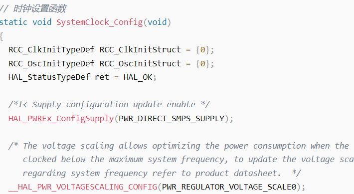
- * 时钟设置函数
- * Fvco: VCO 频率
- * Fsys: 系统时钟频率,也是 PLL1 的 p 分频输出时钟频率
- * Fq: PLL1 的 q 分频输出时钟频率
- * Fs: PLL 输入时钟频率,可以是 HSI,CSI,HSE 等.
- * Fvco = Fs * (plln/pllm) = (Fs/DIVM)*DIVN;
- * Fsys = Fvco/pllp = Fs * (plln/(pllm * pllp));
- * Fq = Fvco/pllq = Fs * (plln/(pllm * pllq));
- *
- *
- * plln: PLL1 倍频系数(PLL 倍频),取值范围:4~512.
- * pllm: PLL1 预分频系数(进 PLL 之前的分频),取值范围:2~56.
- * pllp: PLL1 的 p 分频系数(PLL 之后的分频),分频后作为系统时钟,取值范围:2~128
- * pllq: PLL1 的 q 分频系数(PLL 之后的分频),取值范围:1~128.
- * CPU 频率(rcc_c_ck) = sys_d1cpre_ck = 400Mhz
- * rcc_aclk = rcc_hclk3 = 200Mhz
- * AHB1/2/3/4(rcc_hclk1/2/3/4) = 200Mhz
- * APB1/2/3/4(rcc_pclk1/2/3/4) = 100Mhz
- * FMC 时钟频率 =pll2_r_ck=((25/25) * 512/2) = 256Mhz
- *
- * Example:
- * 外部晶振为 25M 的时候,推荐值:plln = 160, pllm = 5, pllp = 2, pllq = 4.
- * 得到:Fvco = 25 * (160/5) = 800Mhz
- * Fsys = 800/2 = 400Mhz
- * Fq = 800/4 = 200Mhz
- */
- #define PLL_N 160
- #define PLL_M 5
- #define PLL_P 2
- #define PLL_Q 4
- // 时钟设置函数
- static void SystemClock_Config(void)
- {
- RCC_ClkInitTypeDef RCC_ClkInitStruct = {0};
- RCC_OscInitTypeDef RCC_OscInitStruct = {0};
- HAL_StatusTypeDef ret = HAL_OK;
- /*!< Supply configuration update enable */
- HAL_PWREx_ConfigSupply(PWR_DIRECT_SMPS_SUPPLY);
- /* The voltage scaling allows optimizing the power consumption when the device is
- clocked below the maximum system frequency, to update the voltage scaling value
- regarding system frequency refer to product datasheet. */
- __HAL_PWR_VOLTAGESCALING_CONFIG(PWR_REGULATOR_VOLTAGE_SCALE0);
- while(!__HAL_PWR_GET_FLAG(PWR_FLAG_VOSRDY)) {}
- /* Enable HSE Oscillator and activate PLL with HSE as source */
- RCC_OscInitStruct.OscillatorType = RCC_OSCILLATORTYPE_HSE;
- RCC_OscInitStruct.HSEState = RCC_HSE_ON;
- RCC_OscInitStruct.HSIState = RCC_HSI_OFF;
- RCC_OscInitStruct.CSIState = RCC_CSI_OFF;
- RCC_OscInitStruct.PLL.PLLState = RCC_PLL_ON;
- RCC_OscInitStruct.PLL.PLLSource = RCC_PLLSOURCE_HSE;
- RCC_OscInitStruct.PLL.PLLM = PLL_M;
- RCC_OscInitStruct.PLL.PLLN = PLL_N;
- RCC_OscInitStruct.PLL.PLLFRACN = 0;
- RCC_OscInitStruct.PLL.PLLP = PLL_P;
- RCC_OscInitStruct.PLL.PLLR = 2;
- RCC_OscInitStruct.PLL.PLLQ = PLL_Q;
- RCC_OscInitStruct.PLL.PLLVCOSEL = RCC_PLL1VCOWIDE;
- RCC_OscInitStruct.PLL.PLLRGE = RCC_PLL1VCIRANGE_2;
- ret = HAL_RCC_OscConfig(&RCC_OscInitStruct);
- if(ret != HAL_OK)
- {
- while(1) {};
- }
- /* Select PLL as system clock source and configure bus clocks dividers */
- RCC_ClkInitStruct.ClockType = (RCC_CLOCKTYPE_SYSCLK | RCC_CLOCKTYPE_HCLK | RCC_CLOCKTYPE_D1PCLK1 | RCC_CLOCKTYPE_PCLK1 | \
- RCC_CLOCKTYPE_PCLK2 | RCC_CLOCKTYPE_D3PCLK1);
- RCC_ClkInitStruct.SYSCLKSource = RCC_SYSCLKSOURCE_PLLCLK;
- RCC_ClkInitStruct.SYSCLKDivider = RCC_SYSCLK_DIV1;
- RCC_ClkInitStruct.AHBCLKDivider = RCC_HCLK_DIV2;
- RCC_ClkInitStruct.APB3CLKDivider = RCC_APB3_DIV2;
- RCC_ClkInitStruct.APB1CLKDivider = RCC_APB1_DIV2;
- RCC_ClkInitStruct.APB2CLKDivider = RCC_APB2_DIV2;
- RCC_ClkInitStruct.APB4CLKDivider = RCC_APB4_DIV2;
- ret = HAL_RCC_ClockConfig(&RCC_ClkInitStruct, FLASH_LATENCY_3);
- if(ret != HAL_OK)
- {
- while(1) {};
- }
- }
|
.png) STMCU小助手
发布时间:2021-12-22 13:46
STMCU小助手
发布时间:2021-12-22 13:46
 微信公众号
微信公众号
 手机版
手机版