|
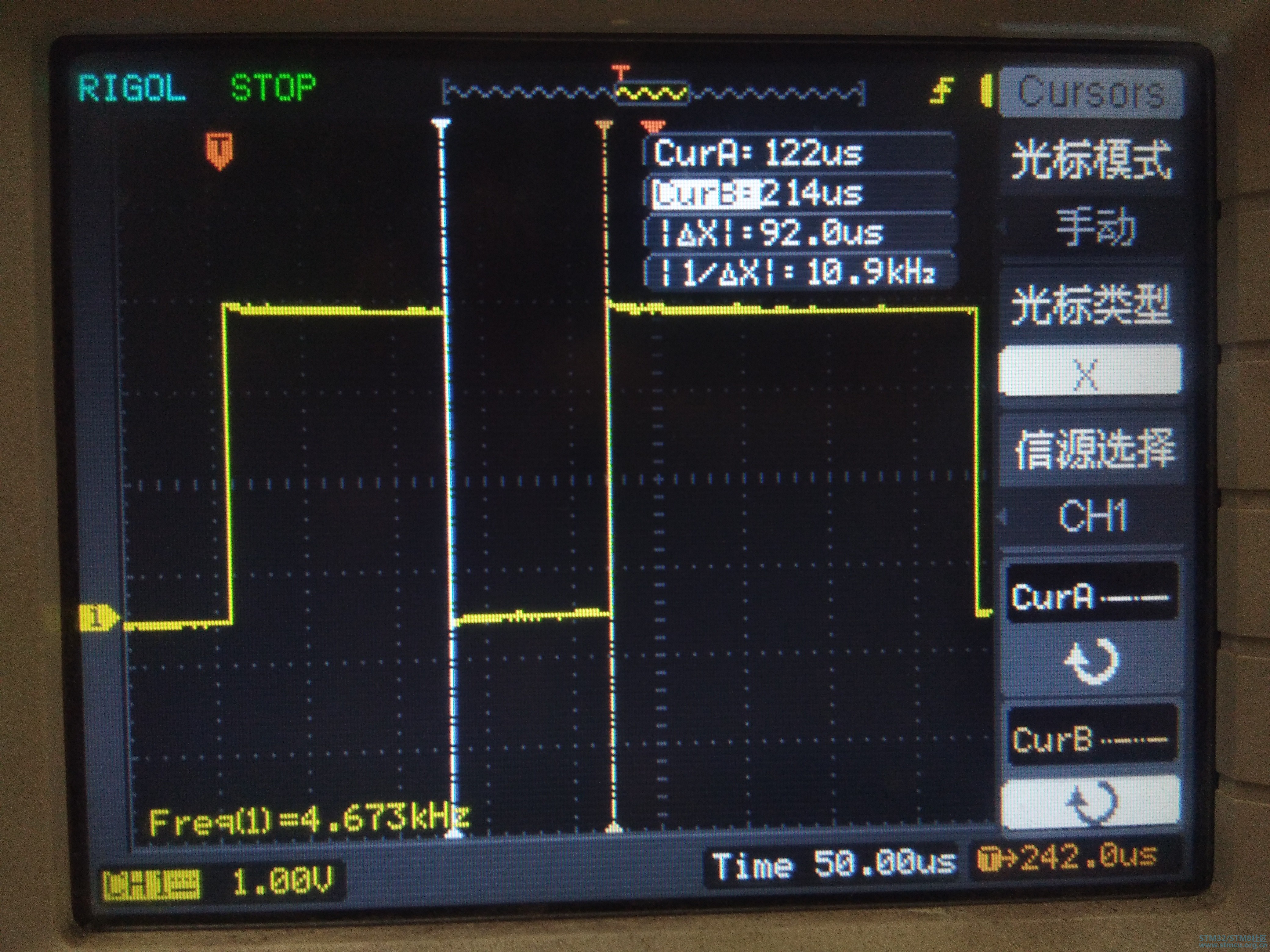
各位大神,请教一下,我有一块Nucleo 64开发板,把MCU换成STM32L072RB。使用LSE作为LPUART的源,用示波器测试PA2(LPUART_TX)发现波特率不准。而且一个字节中高位和低位保持时间不一致。 高位的波特率误差是(8200-9600)/9600=-14.5% 低位的波特率误差是(10900-9600)/9600=13.5% 如图所示 代码如下: /** * @brief Main program * @param None * @retval None */ int main(void) { /* Configure the system clock to 2.097 MHz */ SystemClock_Config(); /* Add your application code here */ /** 配置LSE*/ Configure_LSE(); /** Leds初始化*/ Leds_Init(); /** LPUART初始化*/ Configure_LPUART(); /* Infinite loop */ while (1) { delay_ms(200); printf("-------------------------------------------------------------\r\n"); } } void SystemClock_Config(void) { /* MSI configuration and activation */ LL_RCC_PLL_Disable(); /* Set new latency */ LL_FLASH_SetLatency(LL_FLASH_LATENCY_1); LL_RCC_MSI_Enable(); while(LL_RCC_MSI_IsReady() != 1) { }; LL_RCC_MSI_SetRange(LL_RCC_MSIRANGE_5); LL_RCC_MSI_SetCalibTrimming(0x0); /* Sysclk activation */ LL_RCC_SetAHBPrescaler(LL_RCC_SYSCLK_DIV_1); LL_RCC_SetSysClkSource(LL_RCC_SYS_CLKSOURCE_MSI); while(LL_RCC_GetSysClkSource() != LL_RCC_SYS_CLKSOURCE_STATUS_MSI) { }; /* Set APB1 & APB2 prescaler*/ LL_RCC_SetAPB1Prescaler(LL_RCC_APB1_DIV_1); LL_RCC_SetAPB2Prescaler(LL_RCC_APB2_DIV_1); /* Set systick to 1ms in using frequency set to 2MHz */ LL_Init1msTick(2097000); LL_SYSTICK_SetClkSource(LL_SYSTICK_CLKSOURCE_HCLK); /* Update CMSIS variable (which can be updated also through SystemCoreClockUpdate function) */ LL_SetSystemCoreClock(2097000); /* Enable Power Control clock */ LL_APB1_GRP1_EnableClock(LL_APB1_GRP1_PERIPH_PWR); /* The voltage scaling allows optimizing the power consumption when the device is clocked below the maximum system frequency, to update the voltage scaling value regarding system frequency refer to product datasheet. */ LL_PWR_SetRegulVoltageScaling(LL_PWR_REGU_VOLTAGE_SCALE3); /** Enable SysTick exception request **/ LL_SYSTICK_EnableIT(); } void Configure_LSE(void) { LL_APB1_GRP1_EnableClock(LL_APB1_GRP1_PERIPH_PWR); LL_PWR_EnableBkUpAccess(); /* Enable LSE only if disabled.*/ if (LL_RCC_LSE_IsReady() == 0) { LL_RCC_LSE_Enable(); while (LL_RCC_LSE_IsReady() != 1) { } } } void Leds_Init(void) { LL_GPIO_InitTypeDef gpio_initstruct; /* Enable the LED2 Clock */ LED2_GPIO_CLK_ENABLE(); /* Configure IO in output push-pull mode to drive external LED2 */ gpio_initstruct.Pin = LED2_PIN; gpio_initstruct.Mode = LL_GPIO_MODE_OUTPUT; gpio_initstruct.Speed = LL_GPIO_SPEED_FREQ_LOW; gpio_initstruct.OutputType = LL_GPIO_OUTPUT_PUSHPULL; gpio_initstruct.Pull = LL_GPIO_PULL_NO; LL_GPIO_Init(LED2_GPIO_PORT, &gpio_initstruct); BSP_Led_Off(); } void Configure_LPUART(void) { LL_LPUART_InitTypeDef lpuart_initstruct; /* (1) Enable GPIO clock and configures the LPUART1 pins *******************/ /* (TX on PC.1, RX on PC.0) **********************/ /* Enable the peripheral clock of LUART */ LUART_GPIO_CLK_ENABLE(); /* Configure TX Pin as : Alternate function, High Speed, PushPull, Pull up */ LL_GPIO_SetPinMode(LUART_GPIO_PORT, LUART_TX_PIN, LL_GPIO_MODE_ALTERNATE); LL_GPIO_SetAFPin_0_7(LUART_GPIO_PORT, LUART_TX_PIN, LUART_TX_AF); LL_GPIO_SetPinSpeed(LUART_GPIO_PORT, LUART_TX_PIN, LL_GPIO_SPEED_FREQ_HIGH); LL_GPIO_SetPinOutputType(LUART_GPIO_PORT, LUART_TX_PIN, LL_GPIO_OUTPUT_PUSHPULL); LL_GPIO_SetPinPull(LUART_GPIO_PORT, LUART_TX_PIN, LL_GPIO_PULL_NO); /* Configure RX Pin as : Alternate function, High Speed, PushPull, Pull up */ LL_GPIO_SetPinMode(LUART_GPIO_PORT, LUART_RX_PIN, LL_GPIO_MODE_ALTERNATE); LL_GPIO_SetAFPin_0_7(LUART_GPIO_PORT, LUART_RX_PIN, LUART_RX_AF); LL_GPIO_SetPinSpeed(LUART_GPIO_PORT, LUART_RX_PIN, LL_GPIO_SPEED_FREQ_HIGH); LL_GPIO_SetPinOutputType(LUART_GPIO_PORT, LUART_RX_PIN, LL_GPIO_OUTPUT_OPENDRAIN); LL_GPIO_SetPinPull(LUART_GPIO_PORT, LUART_RX_PIN, LL_GPIO_PULL_NO); /* (3) Enable the LPUART1 peripheral clock and clock source ****************/ LL_APB1_GRP1_EnableClock(LL_APB1_GRP1_PERIPH_LPUART1); /* Set LPUART1 clock source as LSE */ LL_RCC_SetLPUARTClockSource(LL_RCC_LPUART1_CLKSOURCE_LSE); /* (4) Configure LPUART1 functional parameters ********************************/ /* Disable LPUART1 prior modifying configuration registers */ /* Note: Commented as corresponding to Reset value */ // LL_LPUART_Disable(LPUART1); /* Set fields of initialization structure */ /* - BaudRate : 9600 */ /* - DataWidth : LL_LPUART_DATAWIDTH_8B */ /* - StopBits : LL_LPUART_STOPBITS_1 */ /* - Parity : LL_LPUART_PARITY_NONE */ /* - TransferDirection : LL_LPUART_DIRECTION_TX_RX */ /* - HardwareFlowControl : LL_LPUART_HWCONTROL_NONE */ lpuart_initstruct.BaudRate = 9600; lpuart_initstruct.DataWidth = LL_LPUART_DATAWIDTH_8B; lpuart_initstruct.StopBits = LL_LPUART_STOPBITS_1; lpuart_initstruct.Parity = LL_LPUART_PARITY_NONE; lpuart_initstruct.TransferDirection = LL_LPUART_DIRECTION_TX_RX; lpuart_initstruct.HardwareFlowControl = LL_LPUART_HWCONTROL_NONE; /* Initialize LPUART instance according to parameters defined in initialization structure */ LL_LPUART_Init(LPUART1, &lpuart_initstruct); /* (5) Enable LPUART1 **********************************************************/ LL_LPUART_Enable(LPUART1); } int fputc(int ch, FILE *f) { /* Place your implementation of fputc here */ /* e.g. write a character to the USART */ LL_LPUART_TransmitData8(LPUART1, ch); /* Loop until transmit data complete */ /* Wait for TXE flag to be raised */ while (!ConsoleFlag_TXE(LPUART1)) {} return ch; } 请大神们支援! |


STM32L011D4芯片用SWD无法下载程序
求助:STM32L0系列标准库哪里下?
STM32L051低温时LPUART串口波特率异常
STM32L051单片机ADC如何彻底关闭?
STM32L051C8进入低功耗模式电流偏大
STM32L052C8T6通过I2C模拟读16位数
STM32L0的VLCD外接5V会有问题吗
STM32L072RB写Bank2 EEPROM不响应中断
STM32L031无法进入boot
用MDK5.12仿真STM32L011D3,怎么没法子看内部寄存器?
 微信公众号
微信公众号
 手机版
手机版

评分
查看全部评分
因为使用的是MSI时钟。
2)就算换了CPU,如果设置正确的主频,Luart 时钟主频,其波特率还是差不离的;
3)如果您不会设置CPU主频,GPIO 主频,LUART时钟,您大可用STMcubeMX 神器来设定初始化啊
评分
查看全部评分
32768/3=10922(和10900相近)
32768/4=8192(和8200相近)
硬伤,没辄。