|
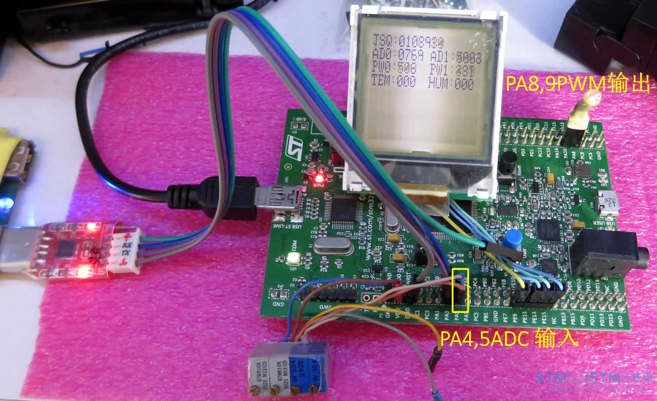
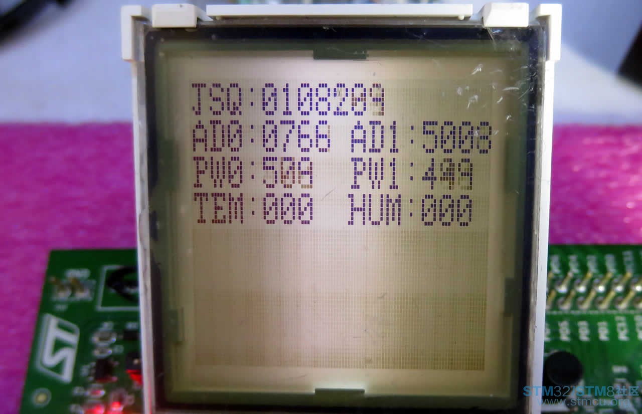
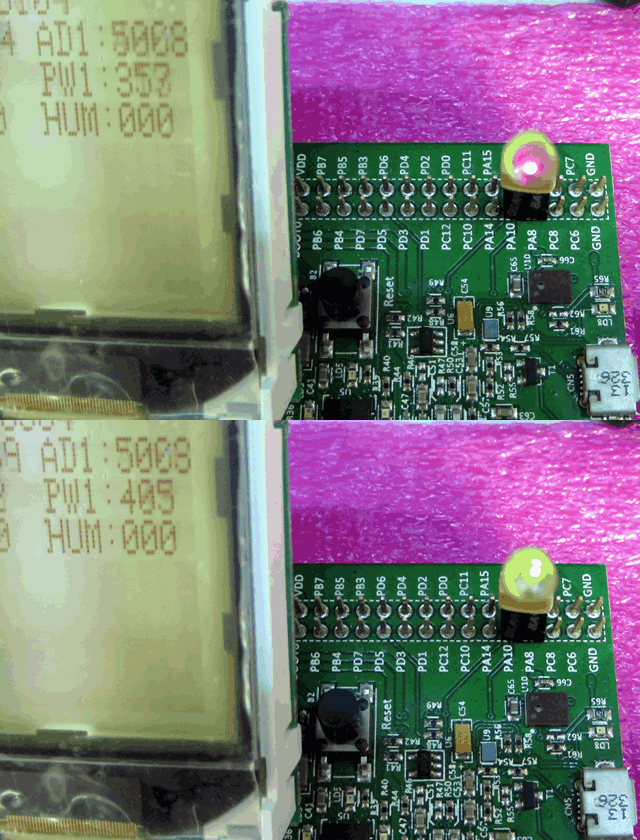
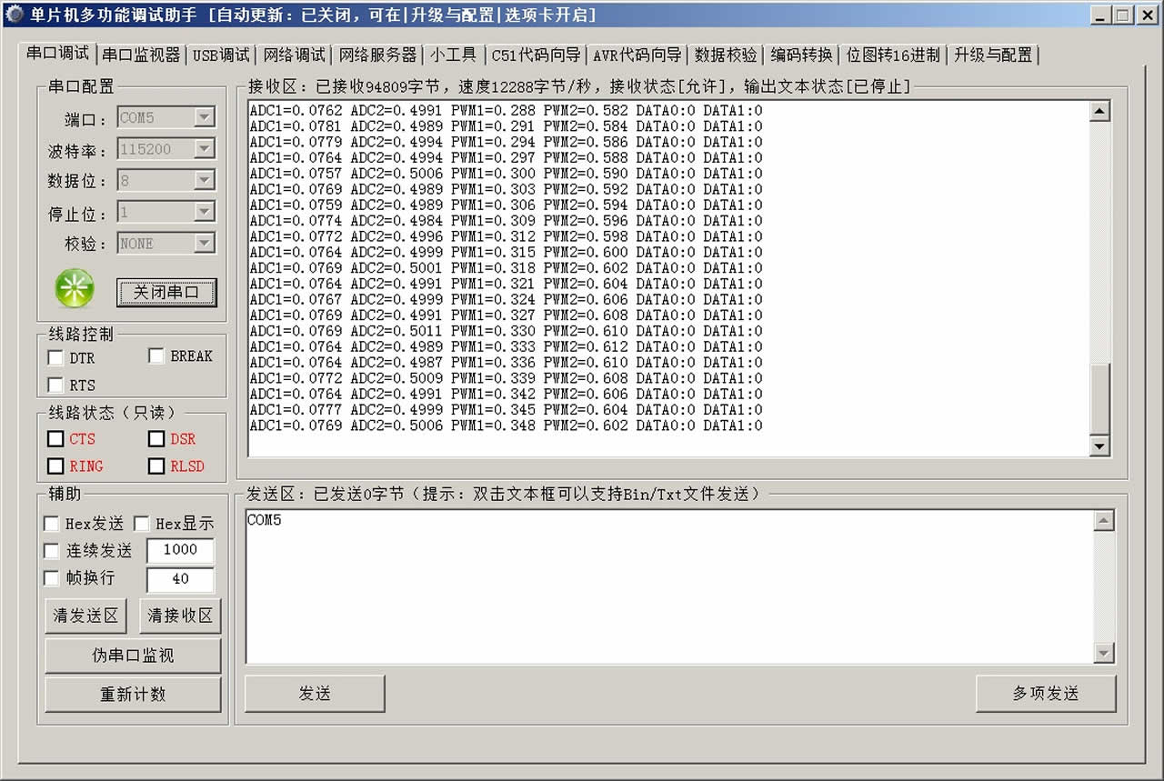
[STM32F401-DISCO开发板]实验一、STM32F401 DISCO开发板介绍,点亮LED [STM32F401-DISCO开发板]实验二、驱显黑白LCD_6903,串口调试 本实验较为简单,设置2论ADC采样和2路PWM输出,并且显示在LCD上同时从串口输出数据。 定义对象: AnalogIn adc0(PA_4); AnalogIn adc1(PA_5); PwmOut pwm0(PA_10); PwmOut pwm1(PA_8); Ticker tick;//Time Interupt Clock //DigitalOut led(LED1); Serial sout(PA_2,PA_3);//(USBTX, USBRX); 定义显示函数: void dispBase(void); void dispMes(void); 定义变量: //DEFINE VARIABLE int32_t jsq; float val0,val1,dut0=0.330f,dut1=0.450f,ddu0=0.003f,ddu1=0.002f; int pdir0=1,pdir1=1,twAddr1=0xBC,twAddr2=0xBB; char twData[2]={0,0}; 定义中断Tick实现程序计数器: void tipInt(void){jsq++;} 定义GPIO[仅仅PWM周期]: void ioInit(void){ pwm0.period(0.003f);//pwm0 pwm1.period(0.004f);//pwm1 } main函数: int main(){ ioInit(); lcdInit(); lcdClear(); dispBase(); tick.attach(&tipInt,0.005f); sout.printf("TEST 2ADC 2PWM a LCD Display\n\r"); while(true){ val0=adc0.read(); val1=adc1.read(); if(dut0>0.810f){pdir0=0;};if(dut0<0.180f){pdir0=1;} if(pdir0==0){dut0 -=ddu0;};if(pdir0==1){dut0 +=ddu0;} pwm0=dut0; if(dut1>0.610f){pdir1=0;};if(dut1<0.160f){pdir1=1;} if(pdir1==0){dut1 -=ddu1;};if(pdir1==1){dut1 +=ddu1;} pwm1=dut1; //i2c.read(twAddr1,twData,2); if((jsq/5)%5==1){dispMes();} sout.printf("ADC1=%0.4f ADC2=%0.4f PWM1=%0.3f PWM2=%0.3f ",val0,val1,dut0,dut1); sout.printf("DATA0:%d DATA1:%d \n\r",twData[0],twData[1]); //led=!led; //wait(0.05); } } 显示固定字符函数: //Display Base Meseger void dispBase(void){ c2l(0,0,19);c2l(1,0,28);c2l(2,0,26);c2l(3,0,40);//JSQ: c2l(0,1,10);c2l(1,1,13);c2l(2,1,0);c2l(3,1,40);//AD0: c2l(9,1,10);c2l(10,1,13);c2l(11,1,1);c2l(12,1,40);//AD1: c2l(0,2,25);c2l(1,2,32);c2l(2,2,0);c2l(3,2,40);//PW0: c2l(9,2,25);c2l(10,2,32);c2l(11,2,1);c2l(12,2,40);//PW1: c2l(0,3,29);c2l(1,3,14);c2l(2,3,22);c2l(3,3,40);//TEM: c2l(9,3,17);c2l(10,3,30);c2l(11,3,22);c2l(12,3,40);//HUM: } 显示采样和PWM输出计数器输出数据: //Display Messeg void dispMes(void){ c2l(4,0,(jsq/1000000)%10);c2l(5,0,(jsq/100000)%10);c2l(6,0,(jsq/10000)%10);c2l(7,0,(jsq/1000)%10);//JSQ: c2l(8,0,(jsq/100)%10);c2l(9,0,(jsq/10)%10);c2l(10,0,(jsq)%10);//JSQ: c2l(4,1,int(val0*10)%10);c2l(5,1,int(val0*100)%10);c2l(6,1,int(val0*1000)%10);c2l(7,1,int(val0*10000)%10);//ad0 c2l(13,1,int(val1*10)%10);c2l(14,1,int(val1*100)%10);c2l(15,1,int(val1*1000)%10);c2l(16,1,int(val1*10000)%10);//ad0 c2l(4,2,int(dut0*10)%10);c2l(5,2,int(dut0*100)%10);c2l(6,2,int(dut0*1000)%10); c2l(13,2,int(dut1*10)%10);c2l(14,2,int(dut1*100)%10);c2l(15,2,int(dut1*1000)%10); c2l(4,3,(twData[0]/100)%10);c2l(5,3,(twData[0]/10)%10);c2l(6,3,(twData[0])%10); c2l(13,3,(twData[1]/100)%10);c2l(14,3,(twData[1]/10)%10);c2l(15,3,(twData[1])%10); } 编译后下载运行结果见照片和截图。照片31为硬件连接;照片32为LCD显示结果;照片33为PWM控制2个LED轮流渐亮暗;截图34为牟尼出口输出的ADC和PWM数据。 |
31

32

33

34

继续点赞 |
| 赞,很不错 |
| 很不错~~ |
| 不错 |
STM32系统中2种数据掉电保护的方法
STM32和Arduino对比,谁更耐打?
STM32 LL为什么比HAL高效?
STM32为何在诸多的单片机中脱颖而出?
F429I-DISC1体验报告(5) 滚动菜单、语言切换的实现丨国庆开发板测评活动
F429I-DISC1体验报告(4) 温度可视化动态图表的实现丨国庆开发板测评活动
STM32串口自动识别波特率的原理
STM32应用过程中与电源相关的案例分享
【经验分享】STM32F4 CAN2只能发送无法接收问题解决
F429I-DISC1体验报告(3) 画板线条绘制和调色功能的实现丨国庆开发板测评活动
 微信公众号
微信公众号
 手机版
手机版
