


.png) STMCU小助手
发布时间:2022-2-12 18:00
STMCU小助手
发布时间:2022-2-12 18:00
|
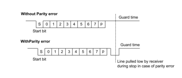
前言 本篇 LAT 的内容简介了 STM32F0 中关于 USART 中 Smartcard 模式的 Guard Time 的设置 问题 客户使用 STM32F091 的 USART 工作于 smartcard 模式用于 7816 通讯,发现不正常。 分析 用示波器观察波形,发现每个数据之间有较长时间的空闲电平。对比文档,这段时间应当是 Guard time. 经查看代码,程序中设置 Guard time (寄存器 USARTx_GTPR 中 GT[7:0]位)为 14。 那么 7816 协议里面是怎么定义 Guard time 的呢? 经查,协议里定义为” The minimum delay between the leading edges of two consecutive characters is named “guard time””。这就是说,规范里定义的 Guard time 实质上是包含了当前字符的时间长度。 那么寄存器里 Guard time 又是怎么定义的呢? 在 Reference Manual 中,有这样的描述:“In transmission, the USART inserts the Guard Time (as programmed in the Guard Time register) between two successive characters.”这就是说,对于STM32F091 来说,其规定的 Guard time 不包含当前字符的时间长度。 结论 由上述分析可以看出,芯片和 7816 规范对于 Guard time 的定义略有差别,因此在程序中需要据此作出相应调整。 那么是否是芯片对此的定义有问题呢?恐怕也不能这么说。从芯片端来看,发送一个字符的时间长度其实已经由波特率决定了,能够单独进行设置的只是在字符发送完成之后插入的那一小段时间。于是,就将这个时间叫 Guard time。可见,它实质上是为了实现 7816 协议的要求,两者本质上没有区别。 如果仔细看文档,里面已经特意说明:“As the Guard Time is measured after the stop bit of the previous character, the GT[7:0] register must be programmed to the desired CGT (Character Guard Time, as defined by the 7816-3 specification) minus 12 (the duration of one character).” 再对照文档中相关的图(如下图),这个问题就很清楚了。 ![J2`0IA6}N_AIXAY9PB65K]M.png](data/attachment/forum/202202/12/180324wa22uuk8z1yh718u.png "J2`0IA6}N_AIXAY9PB65K]M.png")
处理 按照文档说明,修改代码调整 GT[7:0]设置。 |
 微信公众号
微信公众号
 手机版
手机版