





|
拿到开发板有一段时间,看了下资料,使用mbed平台那简直是太简单了,但mbed封装的太严实,实在是不利于我们了解MCU内部运作机理,所以还是要使用ST的库(直接寄存器操作就免了,我不想回到石器时代),现在ST库除了F1系列已经改变,采用新的HAL Drivers的方式,这种方式更友好,更符合软件工程。使用STM32CubeMX把和MCU相关的代码已经生成的90%了,剩下和10%需要自己来完成,所有的中断基本上采用“伪回调”的方式,使用用户更专注于业务算法本身。废话不多说了,直接上代码:& U- ~$ K7 A' I -------------------------------------------------------------------------------传说中的分界线---------------------------------------------------------------------------- main.c #include "stm32l0xx_hal.h" #include "dma.h" #include "i2c.h" y) M% M4 k$ y0 O' ]5 B4 B #include "tim.h" #include "usart.h"! a3 ^4 r8 o' E; b #include "gpio.h" #include "mpu6050.h" #include "visualscope.h" * I7 G" C. m1 n4 Z #include <string.h>0 I8 }4 ^0 Z" ?+ D #include <math.h>& B3 o, [. m; a& v& J * D( O& j% o/ a/ H Q# d1 k /* Private variables ---------------------------------------------------------*/ #define RXSIZE 8 #define TXSIZE 81 g7 l& j; q, N" `. |# P0 c uint8_t rxBuffer[RXSIZE]; uint8_t txBuffer[TXSIZE]; + g+ k4 W4 c, s5 h( R& Y float Angle_accel = 0;8 X8 J( G% F8 `/ j% E: K9 b float Angle_gyro = 0; float Angle_comp = 0;& Y5 @: D8 K& G# g' { uint8_t outAngleData[10]; /* USER CODE BEGIN 0 */" p) |( d. m. _# H* } /*---------------------------------------------------------------------------------------------------------*/2 V- n: Y- w) u$ c _ /* 重力加速度算出的角度 */' T+ y6 `; a: r3 v- m, a) _1 c+ o /*---------------------------------------------------------------------------------------------------------*/ int32_t Calc_AngleAccel() {: W5 k" _9 ]/ B& b. s int32_t value = 0; value = GetAccelValue('x'); if(value > 16384) Angle_accel = -(asin(1) * 180 / 3.1415296); else1 g9 C8 S( D+ ?4 F; ] Angle_accel = -(asin(value * 1.0 / 16384) * 180 / 3.1415296); return value;$ x8 R1 @- L, l' M2 O }: @* U7 a, z1 m- y /*---------------------------------------------------------------------------------------------------------*/ /* 角速度算出来的角度(积分) */+ I4 R& Q- k" D+ M( r /*---------------------------------------------------------------------------------------------------------*/" {$ S- r- P% Z/ M+ k% L* c6 w int32_t Calc_AngleGyro() { int32_t value = 0; 4 c% a6 T: B$ N6 G value = GetGyroValue('y'); Angle_gyro += (value / 16.384 * 0.01); return value;% R( {- b0 @3 { _ } /*---------------------------------------------------------------------------------------------------------*/) Z$ i5 Z! C; t( |: S3 P& I /* 互补滤波求角度 */5 k# p( h [/ D5 ~ /*---------------------------------------------------------------------------------------------------------*/2 }$ T6 N: _9 _; Q float ComplementFilter(int32_t simpleGyro)6 f, J; ]6 e/ @ {% q+ j+ g- _; o/ `( S) M! v Angle_comp = 0.98 * (Angle_comp + -simpleGyro / 16.384 * 0.01) + 0.02 * Angle_accel; 3 J4 j; N9 G0 J& F+ D return Angle_comp;' n& ?* U2 o, g% G2 `: H3 z, U } [7 A+ ~$ f, D5 `2 r, a /*---------------------------------------------------------------------------------------------------------*/9 b! {. k7 [/ M* A- [3 z' d! L /* 输出角度至上位机 */2 ~, [% u" P! U3 h' }0 a /*---------------------------------------------------------------------------------------------------------*/ i* B- K: i& | void VisualScopeAngleOutput()* C8 v1 W8 b1 D/ p5 ? { int AngleValue_Accel,AngleValue_Gyro,AngleValue_Comp; uint16_t crcValue; + v: ~ i8 B8 A+ c8 h; M AngleValue_Accel = ceil(Angle_accel * 10 -0.5);/ c1 P4 [9 [5 ?* P8 E AngleValue_Gyro = ceil(Angle_gyro * 10 - 0.5); AngleValue_Comp = ceil(Angle_comp * 10 - 0.5); * f' K4 i$ P+ l# I4 s! Y: f outAngleData[0] = AngleValue_Accel & 0xFF; outAngleData[1] = AngleValue_Accel >> 8;) ]8 p: R2 o7 d1 P outAngleData[2] = AngleValue_Gyro & 0xFF;4 ^* {7 [: L6 {- b7 Q9 d, t outAngleData[3] = AngleValue_Gyro >> 8; outAngleData[4] = AngleValue_Comp & 0xFF;' v% a4 t. G, [0 a( C' ? outAngleData[5] = AngleValue_Comp >> 8; //计算CRC/ g; M1 M# m; M crcValue = CRC_CHECK(outAngleData,8);6 z# [2 ^% v0 u8 K+ @ outAngleData[8] = crcValue & 0xFF;7 x, n; X% g& _9 j8 O1 x4 c. l, w outAngleData[9] = crcValue >> 8;3 |. J [0 K( W //发送至上位机" R' L& `+ W# M+ d+ ?" _ HAL_UART_Transmit_DMA(&huart2,outAngleData,sizeof(outAngleData)); }% ~2 F6 w8 x$ w3 L* c+ n; V /* USER CODE END 0 */% P& [% p1 b# i p- ` /* Private function prototypes -----------------------------------------------*/7 Q9 a1 [0 `& K6 E1 r* m; w/ j void SystemClock_Config(void); 3 I/ h8 K# ?* ~! Z- N 硬件连接图: 
波形图: 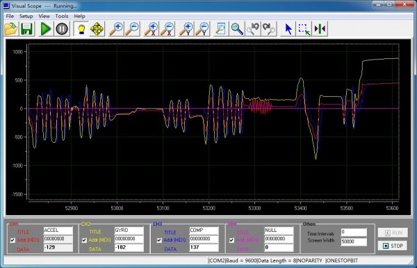
最后加一个视频: STM32L053 演示 |
STM32 5V FT引脚疑问
STM32MP1 自举程序编程:USB DFU/USART 协议全解析
STM32大神笔记,超详细单片机学习汇总资料
实战经验 | 如何配置STM32MP257的RMII Switch
简单实用!STM32硬件错误的调试技巧
OpenSTLinux 6.1发布:M33-TD加持+安全升级,STM32MPU开发效率翻倍!
STM32MP135 MP157 MP257 CoreMark移植&&跑分对比&&多核心负载不均衡问题排查与解决
STM32系列芯片之间相互移植注意事项
STM32如何成为现代科技的隐形引擎
STM32--STM32 微控制器详解
 微信公众号
微信公众号
 手机版
手机版


#include "i2c.h"! c9 s/ m! D* u; Q& `8 s8 r8 G
0 ?5 T/ y, a r3 r# s! f
#include "gpio.h"
6 p! K2 y1 d! a2 X' t- a3 g4 u
/* USER CODE BEGIN 0 */" |' q% l3 T0 J2 {0 ] F, c
/* USER CODE END 0 */# V9 {. ]2 y7 K' [
|# D3 Q9 T2 B
I2C_HandleTypeDef hi2cx;
/* I2C1 init function */2 x7 ^# ]! F# X& y5 q+ A( Q
void MX_I2C1_Init(void): S- M" C' @: l! f. l
{
hi2cx.Instance = I2C1;
hi2cx.Init.Timing = 0x20D22930;/ f6 S" B9 W" J. }2 y7 u- Y
hi2cx.Init.OwnAddress1 = 0;
hi2cx.Init.AddressingMode = I2C_ADDRESSINGMODE_7BIT;
hi2cx.Init.DualAddressMode = I2C_DUALADDRESS_DISABLED;: w2 y( ~* `* _4 L/ J, r
hi2cx.Init.OwnAddress2 = 0;3 I* i+ u5 R7 s& l! w* D; e6 p: o
hi2cx.Init.OwnAddress2Masks = I2C_OA2_NOMASK;
hi2cx.Init.GeneralCallMode = I2C_GENERALCALL_DISABLED;
hi2cx.Init.NoStretchMode = I2C_NOSTRETCH_DISABLED;3 o% v4 O$ m" m0 E, l% G
HAL_I2C_Init(&hi2cx);
- {0 W) S1 j0 i. h2 k7 q4 N* k
/**Configure Analogue filter
*/7 z6 N! ?6 s( t5 j O% j; B& q
HAL_I2CEx_AnalogFilter_Config(&hi2cx, I2C_ANALOGFILTER_ENABLED);
) {& w6 @+ F" [, Q, \: p
}& s! }4 v' p+ u: U. l; m
( N7 c' x, }% p
void HAL_I2C_MspInit(I2C_HandleTypeDef* hi2c)
{- a7 a0 M. t) }/ n/ ]2 q! |3 b
GPIO_InitTypeDef GPIO_InitStruct;
if(hi2c->Instance==I2C1)9 p# s1 o$ F4 [1 \: _# v
{
/* Peripheral clock enable */
__I2C1_CLK_ENABLE();
+ c/ Q* G3 x% y& X7 H9 Q" e" ?
/**I2C1 GPIO Configuration 5 p1 A! R4 q5 `- A# ?' z
PB6 ------> I2C1_SCL! j5 l( o. G( f4 i, [! b
PB7 ------> I2C1_SDA" Z, b# G( W0 f# \# S
*/3 ^8 u, w$ i7 G: `% n* Y3 o
GPIO_InitStruct.Pin = GPIO_PIN_6|GPIO_PIN_7;: {: |/ }0 J8 I9 `1 o7 E
GPIO_InitStruct.Mode = GPIO_MODE_AF_OD;
GPIO_InitStruct.Pull = GPIO_NOPULL;
GPIO_InitStruct.Speed = GPIO_SPEED_HIGH;2 B" F( r) H; X9 j( o
GPIO_InitStruct.Alternate = GPIO_AF1_I2C1;
HAL_GPIO_Init(GPIOB, &GPIO_InitStruct);
0 R6 l( D! s. L
}
}: h6 ?0 L: h/ H* d
0 f# V9 k n7 `* d
void HAL_I2C_MspDeInit(I2C_HandleTypeDef* hi2c)6 e, Q$ G) x' D* O h: F1 a
{
if(hi2c->Instance==I2C1)9 h, A3 T" P% i7 p' v& k" W I; z
{
/* Peripheral clock disable */6 v% H( |1 l% G4 T
__I2C1_CLK_DISABLE();' p* w0 n) v6 h/ d7 L) X
/**I2C1 GPIO Configuration F1 T' [. Z6 J- H0 z a/ i
PB6 ------> I2C1_SCL
PB7 ------> I2C1_SDA$ N. ?2 S# t, k/ I% p* t
*/( [/ R8 m0 x2 R! O# z- f( s
HAL_GPIO_DeInit(GPIOB, GPIO_PIN_6|GPIO_PIN_7); a j% p7 _7 ~/ V7 z& [6 M
8 S# G+ g0 V: ^9 n- F
}" g6 }2 ~# }. }9 Z) U& L
}6 d' s4 p$ ?0 d* u9 O, \2 u8 {
------------------------------------------------------------------------------- 传说中的分界线 ----------------------------------------------------------------------------
usart.c5 v6 d( ?' y# D6 ~6 ]" Z* {/ y
#include "usart.h"
3 O/ h( x0 F# a0 f# L
#include "gpio.h"
#include "dma.h". o5 y; N2 s7 T R
# v; b2 L. |2 U" k7 h* b9 W: X; V6 s
/* USER CODE BEGIN 0 */ u2 {' [3 j& ]. ]- {
8 a6 D! e* Q5 E6 v ? o
/* USER CODE END 0 */6 U/ i7 m, P4 E+ h
UART_HandleTypeDef huart2;1 C" L" R6 L& Z& ]5 `" }; P, n
DMA_HandleTypeDef hdma_usart2_rx; x; f9 k$ O% a) P
DMA_HandleTypeDef hdma_usart2_tx;, E7 e: e7 X7 Y" L
4 I' O4 R& _5 Z) P' B* x
/* USART2 init function */
% J9 N# `1 W2 Y
void MX_USART2_UART_Init(void)
{2 U+ Q* M6 G/ Z. t) J& Z# p5 N' c
5 g4 h3 ?5 f4 w6 D2 P/ n/ I& f
huart2.Instance = USART2;7 e/ ]' l' F' i; \+ P
huart2.Init.BaudRate = 9600;, |+ a5 R. S% U
huart2.Init.WordLength = UART_WORDLENGTH_8B;, H& C: h3 A9 Z
huart2.Init.StopBits = UART_STOPBITS_1;
huart2.Init.Parity = UART_PARITY_NONE;) |4 J5 S- N& ?
huart2.Init.Mode = UART_MODE_TX_RX;0 x4 z k6 ?, |
huart2.Init.HwFlowCtl = UART_HWCONTROL_NONE;( t$ j0 r2 Y0 v6 C/ ^1 |* A" w
huart2.Init.OverSampling = UART_OVERSAMPLING_16;
huart2.Init.OneBitSampling = UART_ONEBIT_SAMPLING_DISABLED;, Y/ A" p# H1 B8 @4 n D1 ?
huart2.AdvancedInit.AdvFeatureInit = UART_ADVFEATURE_NO_INIT;- l, H' O- [4 W( U3 K9 g
HAL_UART_Init(&huart2);/ |$ {1 W. }3 ^1 l' V4 T: _
0 a) U! A0 g9 O! r( e
}
void HAL_UART_MspInit(UART_HandleTypeDef* huart)6 E C, p/ P( o" Y
{
6 e/ e; w) ~# w" _) d. Y
GPIO_InitTypeDef GPIO_InitStruct;
if(huart->Instance==USART2)9 g) ?9 r4 _) @: Z& ?/ O
{
/* Peripheral clock enable */
__USART2_CLK_ENABLE();
* X1 W% u, \5 _+ k K0 q( u1 ?1 C- h
/**USART2 GPIO Configuration % J; D' \' H4 e
PA2 ------> USART2_TX
PA3 ------> USART2_RX+ G( X! H1 G# k' A) R3 l0 K
*/
GPIO_InitStruct.Pin = GPIO_PIN_2;$ A2 R. r! g; r+ Y% ^0 A- Y
GPIO_InitStruct.Mode = GPIO_MODE_AF_PP;
GPIO_InitStruct.Pull = GPIO_NOPULL;6 W8 G7 @+ B, \& F" E! ?
GPIO_InitStruct.Speed = GPIO_SPEED_HIGH;
GPIO_InitStruct.Alternate = GPIO_AF4_USART2;4 k8 r. ]! b a+ W% B s w$ a' k
HAL_GPIO_Init(GPIOA, &GPIO_InitStruct);
GPIO_InitStruct.Pin = GPIO_PIN_3;1 {: N# U5 {2 m' F% V+ O7 r
GPIO_InitStruct.Mode = GPIO_MODE_AF_PP;& j1 f8 o. _. k; U6 t7 [
GPIO_InitStruct.Pull = GPIO_NOPULL;
GPIO_InitStruct.Speed = GPIO_SPEED_LOW;
GPIO_InitStruct.Alternate = GPIO_AF4_USART2;
HAL_GPIO_Init(GPIOA, &GPIO_InitStruct);) |: c( h! V9 I8 \ y
/* Peripheral DMA init*/
hdma_usart2_rx.Instance = DMA1_Channel5;) P# W- }- J' l2 x* L
hdma_usart2_rx.Init.Request = DMA_REQUEST_4;0 A- l P7 O* u/ |0 C
hdma_usart2_rx.Init.Direction = DMA_PERIPH_TO_MEMORY;
hdma_usart2_rx.Init.PeriphInc = DMA_PINC_DISABLE;
hdma_usart2_rx.Init.MemInc = DMA_MINC_ENABLE;
hdma_usart2_rx.Init.PeriphDataAlignment = DMA_PDATAALIGN_BYTE;
hdma_usart2_rx.Init.MemDataAlignment = DMA_MDATAALIGN_BYTE;
hdma_usart2_rx.Init.Mode = DMA_NORMAL;
hdma_usart2_rx.Init.Priority = DMA_PRIORITY_LOW;! O5 S/ l6 C+ `% V% T8 s
HAL_DMA_Init(&hdma_usart2_rx);
__HAL_LINKDMA(huart,hdmarx,hdma_usart2_rx);
q! U2 M! |% J2 A4 s/ a; N
hdma_usart2_tx.Instance = DMA1_Channel4;
hdma_usart2_tx.Init.Request = DMA_REQUEST_4;7 g7 I% G5 F( N- M- u+ L! f7 @
hdma_usart2_tx.Init.Direction = DMA_MEMORY_TO_PERIPH;$ j, g, p+ h# c( P, t8 P3 y
hdma_usart2_tx.Init.PeriphInc = DMA_PINC_DISABLE;
hdma_usart2_tx.Init.MemInc = DMA_MINC_ENABLE;
hdma_usart2_tx.Init.PeriphDataAlignment = DMA_PDATAALIGN_BYTE;8 M# }$ Q+ W, k4 \( q* R
hdma_usart2_tx.Init.MemDataAlignment = DMA_MDATAALIGN_BYTE;
hdma_usart2_tx.Init.Mode = DMA_NORMAL;3 ]' n. M/ f- ~% q- ^, M6 U9 O
hdma_usart2_tx.Init.Priority = DMA_PRIORITY_LOW;7 k& K H; B' h0 a3 m) V
HAL_DMA_Init(&hdma_usart2_tx);& P! i! x& Y' z. `2 K
__HAL_LINKDMA(huart,hdmatx,hdma_usart2_tx);) j3 y! ?2 l" t4 A$ s
}, ~4 Z' V3 _& T, h0 j0 P
}
5 t$ T1 f6 z# Z5 ]2 O5 B( W
void HAL_UART_MspDeInit(UART_HandleTypeDef* huart)
{
if(huart->Instance==USART2)
{6 D1 c9 r5 K: U b! R
/* Peripheral clock disable *// a& V- r* ^" K9 L; Q/ D; P/ [" M q9 B
__USART2_CLK_DISABLE();
1 C5 z5 r. ^: [; C2 {! ~ S
/**USART2 GPIO Configuration
PA2 ------> USART2_TX& |* x0 ^5 y$ G4 T; f
PA3 ------> USART2_RX
*/5 a8 w7 f* {. `, p! G
HAL_GPIO_DeInit(GPIOA, GPIO_PIN_2|GPIO_PIN_3);
/* Peripheral DMA DeInit*/
HAL_DMA_DeInit(huart->hdmarx);
HAL_DMA_DeInit(huart->hdmatx);# T! F0 g9 V% Q# k8 q. k. q7 w
}
} i' n. T4 |$ l
------------------------------------------------------------------------------- 传说中的分界线 ----------------------------------------------------------------------------( ~) L V4 X% ]2 f. i6 }
mpu6050.c
#include "stm32l0xx_hal.h"
#include "MPU6050.h"8 M& D4 M8 R, ^' \1 c
//各坐标轴上静止偏差(重力,角速度)
int16_t offsetAccelX = -195;
int16_t offsetAccelY = 560;
int16_t offsetAccelZ = -169;8 v3 J w2 @1 |( l, y; q
int16_t offsetGyroX = 12;' @* L/ N+ F; O7 p/ H# J" o
int16_t offsetGyroY = 33;2 O1 G$ S5 N0 r2 i% g
int16_t offsetGyroZ = 4;, H' ?: \) m/ V( t
. t! O. K2 Y4 ~
extern I2C_HandleTypeDef hi2cx;
6 _/ K) T0 c2 J0 k7 p, @- L
//**************************************
//向I2C设备写入一个字节数据. m7 z- K' g; H
//**************************************/ g, ? P+ V, U |/ {' c- T; _
void Single_WriteI2C(uint8_t REG_Address,uint8_t REG_data)
{ \5 v3 R/ ?7 w
uint8_t rxData[2] = {REG_Address,REG_data};
while(HAL_I2C_Master_Transmit(&hi2cx,SlaveAddress,rxData,2,5000) != HAL_OK)4 u6 ?3 a4 d8 o' _
{" J% g! \; I' ]- l4 |
if(HAL_I2C_GetError(&hi2cx) != HAL_I2C_ERROR_AF)
{}
}
}6 W* V* [% b! z: }
//**************************************5 f, n1 m* Z. `0 \/ Q7 L( E0 y1 _
//从I2C设备读取一个字节数据/ j5 h- q- O; U& L+ t$ q3 o m
//**************************************, I/ r2 X3 f# w* s2 r; L
uint8_t Single_ReadI2C(uint8_t REG_Address), Q4 {0 B5 r! \) P; l
{
uint8_t REG_data;
while(HAL_I2C_Master_Transmit(&hi2cx,SlaveAddress,®_Address,1,5000) != HAL_OK) g( V3 O+ D2 R8 Z% h. T+ M
{& ?# G2 k, s; X3 @7 @- |
if(HAL_I2C_GetError(&hi2cx) != HAL_I2C_ERROR_AF)# \1 \% u9 y" `! M; d& R* K
{} t6 N9 \5 P, b$ s
}
if(HAL_I2C_Master_Receive(&hi2cx,SlaveAddress+1,®_data,1,5000) != HAL_OK)
{
if(HAL_I2C_GetError(&hi2cx) != HAL_I2C_ERROR_AF)5 |0 _. Z: k1 O! U
{}0 b: `' v0 r0 B6 b) @) }( w& U1 g
}2 u8 R- t; G/ E/ r0 t2 n
return REG_data;
}
//**************************************
//初始化MPU6050
//**************************************
void InitMPU6050()' P1 _' l7 Y" X6 J8 U. p
{
Single_WriteI2C(PWR_MGMT_1, 0x00); //解除休眠状态
* h; ?/ m1 e# J2 B2 }
Single_WriteI2C(SMPLRT_DIV, 0x07);1 A1 L1 F" G* I( }( @
Single_WriteI2C(CONFIG, 0x06);
Single_WriteI2C(GYRO_CONFIG, 0x18);
' g6 c/ }& T( k9 W8 G
Single_WriteI2C(ACCEL_CONFIG, 0x01);3 s J$ u" O! T$ M" P% \, i9 `
}. C; a3 _% d8 ~. |0 c" b; ]- k
//**************************************' I/ k" g& X' [4 D9 |( g
//合成数据3 }+ [) V ?/ H5 N' Z9 j3 }
//**************************************# ]4 X% ?7 X5 K+ b
int16_t GetMPUOutValue(uint8_t REG_Address)
{
int16_t result;% E- z, l) t/ y% z
uint8_t H,L;. G8 j2 X6 ~- Q
H=Single_ReadI2C(REG_Address);! P# [$ C5 q- U6 h- ^$ x9 }* i6 o
L=Single_ReadI2C(REG_Address+1);
result = (H<<8)+L;
return result; //合成数据
}
! [! E8 S, n! a
//**************************************
//取某一轴上的加速度数据
//**************************************9 g6 F2 ]- g' l$ |* W$ E( v
int16_t GetAccelValue(char axis)! G1 Z/ H/ g7 N' }+ z
{
int16_t result = 0;4 c) E/ l# e) s/ W4 o0 B% V
switch(axis)
{
case 'x':! d# H5 U- {9 y! q; O7 `
case 'X':; T# r4 Y2 C9 H
{8 h$ {, [" F4 a* i# i
result = GetMPUOutValue(ACCEL_XOUT_H) - offsetAccelX;
}* K5 Y/ a4 Y- a
break;, c* ~9 | r: L9 T& x4 a
case 'y':5 y" V9 G3 C L
case 'Y':
{
result = GetMPUOutValue(ACCEL_YOUT_H) - offsetAccelY;
}. e- x/ a4 y- K* W: _
break;
case 'z':
case 'Z':
{6 q7 v; r" O& U
result = GetMPUOutValue(ACCEL_ZOUT_H) - offsetAccelZ;
}
break;( G, K7 s& }$ {
}4 ^ C6 l2 R. ]* \0 F
return result;
}
//**************************************
//取某一轴上的角速度数据/ l0 n+ ^7 c6 r, D# b+ D
//**************************************2 O4 ^4 U5 m4 g5 q3 H, o
int16_t GetGyroValue(char axis)+ }$ E- j6 `2 s: ?; D* B0 S
{
int16_t result = 0;
switch(axis)
{$ B/ H# I, i9 a5 Q/ M
case 'x':
case 'X':
{9 [% H1 s" t6 ` n: f2 t4 g) h
result = GetMPUOutValue(GYRO_XOUT_H) - offsetGyroX;
}
break;
case 'y':
case 'Y':
{
result = GetMPUOutValue(GYRO_YOUT_H) - offsetGyroY;0 @! i+ g6 V3 j8 H# o% N! n3 f
}
break;
case 'z':
case 'Z':
{& B( I9 r' Z) m# z6 B
result = GetMPUOutValue(GYRO_ZOUT_H) - offsetGyroZ;
}, E J4 Z4 o: D- ]- E
break;; L" w# I3 ]2 ~: a
}
return result;
}
评分
查看全部评分
{4 H( ~0 ?# R/ P% ?
/* USER CODE BEGIN 1 */
5 D' Q) o4 I) m
/* USER CODE END 1 */
1 T* C) b8 o5 Y6 C2 Q6 M
/* MCU Configuration----------------------------------------------------------*/6 s0 D5 R+ R3 z% y' T4 O. Q: S5 f1 i' r
! W6 e. k$ w8 B
/* Reset of all peripherals, Initializes the Flash interface and the Systick. */
HAL_Init();* m! @; d! B/ p% a, o( [# L0 _
/* Configure the system clock */
SystemClock_Config();
" \* L) \8 L' l$ Y9 W% P5 ^
/* System interrupt init*/. O( {5 h1 Y; I* ~0 @1 L
HAL_NVIC_SetPriority(SysTick_IRQn, 0, 0);' w6 |2 }% {0 H% d+ Z& Z% d, Y
/* Initialize all configured peripherals */8 o) \& c: x K/ @
MX_GPIO_Init();' E* E1 |! f3 ?8 A
MX_DMA_Init();3 K0 W) }6 J/ r0 A
MX_I2C1_Init();3 O- J ?' z; [. Z8 }( ]% C; e- u
MX_TIM2_Init();
MX_USART2_UART_Init();% @$ L% k4 {' q: n7 L! k: P
InitMPU6050();+ t+ e2 r$ Q" ?. C& n: m+ T& ?9 |
; ?( W5 d& Z. A- s, Q; v, _- O2 t
/* USER CODE BEGIN 2 */) m% c, F5 ]# z3 M# w4 f7 o
HAL_UART_Receive_DMA(&huart2,rxBuffer,RXSIZE);& F9 g8 U, B$ F, }, q- y6 A% U
HAL_TIM_Base_Start_IT(&htim2);
/* USER CODE END 2 */
/* USER CODE BEGIN 3 */) \$ i* A* X' B8 |4 i* b( d4 M
/* Infinite loop */' M4 z* L3 f( S x7 X0 j1 V
while (1)
{
HAL_GPIO_TogglePin(GPIOA,GPIO_PIN_5);, y6 k% x5 x& n* |) B, `, D
VisualScopeAngleOutput();. U8 e8 I: }1 ~. H& Z8 i6 @9 P
HAL_Delay(100);; r/ d, F5 I3 A5 o% I3 k) V
}+ R o% \5 q6 ~
/* USER CODE END 3 */ o3 R& g* A, u, d; }/ f3 S
} _2 E( D. m8 F/ V d( P5 r
/** System Clock Configuration. t4 ?: U, b, d! V# O% q
*/) Y1 A( { O+ V' ~3 B0 M; ?
void SystemClock_Config(void)* A, L8 X2 ^/ Z% R8 a
{
$ A9 |% J8 W9 i. r ~4 `0 q
RCC_ClkInitTypeDef RCC_ClkInitStruct;7 Q+ R# B( `0 c; L$ Z+ p0 M# \- J) Z5 n
RCC_PeriphCLKInitTypeDef PeriphClkInit;
RCC_OscInitTypeDef RCC_OscInitStruct;- J/ f' _& R) v+ Z& X% @
__PWR_CLK_ENABLE();8 G9 o) p+ y4 D& w# k) r
$ z! H: |. s0 o
__HAL_PWR_VOLTAGESCALING_CONFIG(PWR_REGULATOR_VOLTAGE_SCALE1);
RCC_OscInitStruct.OscillatorType = RCC_OSCILLATORTYPE_HSI;( M$ ~0 Q% U4 s+ M! e+ N5 Q
RCC_OscInitStruct.HSIState = RCC_HSI_ON;, c) V/ y" F8 s" ]8 ^/ H
RCC_OscInitStruct.HSICalibrationValue = 16;
RCC_OscInitStruct.PLL.PLLState = RCC_PLL_ON;
RCC_OscInitStruct.PLL.PLLSource = RCC_PLLSOURCE_HSI;
RCC_OscInitStruct.PLL.PLLMUL = RCC_PLLMUL_6;
RCC_OscInitStruct.PLL.PLLDIV = RCC_PLLDIV_3;
HAL_RCC_OscConfig(&RCC_OscInitStruct);
1 K2 G+ C! Z+ o( S
RCC_ClkInitStruct.ClockType = RCC_CLOCKTYPE_SYSCLK;
RCC_ClkInitStruct.SYSCLKSource = RCC_SYSCLKSOURCE_PLLCLK;
RCC_ClkInitStruct.AHBCLKDivider = RCC_SYSCLK_DIV1;
RCC_ClkInitStruct.APB1CLKDivider = RCC_HCLK_DIV1;
RCC_ClkInitStruct.APB2CLKDivider = RCC_HCLK_DIV1;
HAL_RCC_ClockConfig(&RCC_ClkInitStruct, FLASH_LATENCY_1);
$ A. \ [$ [! \. b2 K/ S5 D
PeriphClkInit.PeriphClockSelection = RCC_PERIPHCLK_USART2;4 z# {% G/ B7 j- n
PeriphClkInit.Usart2ClockSelection = RCC_USART2CLKSOURCE_PCLK1;
HAL_RCCEx_PeriphCLKConfig(&PeriphClkInit);0 r: z: } E# v5 H, [- @
% P! [/ @8 k+ h1 ]) i! e
__SYSCFG_CLK_ENABLE();5 _" V% \/ d* J' b
0 z# l: [0 f* ?8 ]/ P# n
}
/* USER CODE BEGIN 4 */
void HAL_UART_RxCpltCallback(UART_HandleTypeDef *huart)
{+ A+ T0 l* T2 I* I8 F6 H4 s
if(huart->Instance == USART2)
{
memcpy(txBuffer,rxBuffer,RXSIZE);
HAL_UART_Receive_DMA(huart,rxBuffer,RXSIZE);
HAL_UART_Transmit_DMA(huart,txBuffer,TXSIZE);
}* H9 Y, O. g n% Y" n) G- h
}7 U% Y8 v$ ^0 E# ], [0 I" E
c- R1 \, v& g. \- V9 N/ ^/ l
void HAL_UART_TxCpltCallback(UART_HandleTypeDef *huart)
{. X6 `9 W; U) k. D
}
void HAL_TIM_PeriodElapsedCallback(TIM_HandleTypeDef *htim)
{" B L+ K2 [1 [$ i* |# o! @# m
int32_t GyroValue;
Calc_AngleAccel();
GyroValue = Calc_AngleGyro();
ComplementFilter(GyroValue);, T3 O/ @% q e% J7 {. a! o
}
使用DMA方式,接收发送数据必须是个固定长度。
如果是长度不固定,你使用中断方式,然后加起止,停止标志位来判断。
好的,多谢指点!
请问应该注意什么地方
我使用是没有问题的呀。