|
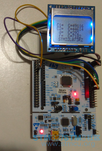
在色彩识别仪的设计中,主要是通过脉冲计数的方式来获取色彩值,因此对脉冲计数功能的实现是必不可少的。 在STM32L073开发板的基础上,配以LCD5110液晶显示器即可构造一个简单的脉冲计数器。LCD5110与STM32L073的连接如下表所示:
那么外部的计数脉冲如何获得呢?最简单的方法就是使用LCD5110的时钟信号SCLK来提供。 为了实现脉冲计数功能,并将计数值显示到LCD5110上,可在STM32L073RZ-Nucleo例程的TIM_InputCapture 的基础上进行改造来实现,主要的任务是添加LCD5110函数。
为了控制LCD5110各引脚的高低电平,相关的输出引脚定义如下: - #define SetLCD_SCLK_High() { HAL_GPIO_WritePin(GPIOC, GPIO_PIN_3, GPIO_PIN_SET);}
- #define SetLCD_SCLK_Low() { HAL_GPIO_WritePin(GPIOC, GPIO_PIN_3, GPIO_PIN_RESET);}
- #define SetLCD_SDIN_High() { HAL_GPIO_WritePin(GPIOC, GPIO_PIN_2, GPIO_PIN_SET);}
- #define SetLCD_SDIN_Low() { HAL_GPIO_WritePin(GPIOC, GPIO_PIN_2, GPIO_PIN_RESET);}
- #define SetLCD_DC_High() { HAL_GPIO_WritePin(GPIOC, GPIO_PIN_1, GPIO_PIN_SET);}
- #define SetLCD_DC_Low() { HAL_GPIO_WritePin(GPIOC, GPIO_PIN_1, GPIO_PIN_RESET);}
- #define SetLCD_RST_High() { HAL_GPIO_WritePin(GPIOC, GPIO_PIN_0, GPIO_PIN_SET);}
- #define SetLCD_RST_Low() { HAL_GPIO_WritePin(GPIOC, GPIO_PIN_0, GPIO_PIN_RESET);}
- #define SetS2_High() { HAL_GPIO_WritePin(GPIOA, GPIO_PIN_0, GPIO_PIN_SET);}
- #define SetS2_Low() { HAL_GPIO_WritePin(GPIOA, GPIO_PIN_0, GPIO_PIN_RESET);}
- #define SetS3_High() { HAL_GPIO_WritePin(GPIOA, GPIO_PIN_1, GPIO_PIN_SET);}
- #define SetS3_Low() { HAL_GPIO_WritePin(GPIOA, GPIO_PIN_1, GPIO_PIN_RESET);}
- void LCD_Init(void)
- {
- //SCLK--PC.3
- //DIN--PC.2
- //DC--PC.1
- //RST--PC.0
- __HAL_RCC_GPIOC_CLK_ENABLE();
- GPIO_InitTypeDef GPIO_InitStruct;
- GPIO_InitStruct.Pin = GPIO_PIN_3| GPIO_PIN_2|GPIO_PIN_1| GPIO_PIN_0;
- GPIO_InitStruct.Mode = GPIO_MODE_OUTPUT_PP;
- GPIO_InitStruct.Pull = GPIO_PULLUP;
- GPIO_InitStruct.Speed = GPIO_SPEED_FAST;
- HAL_GPIO_Init(GPIOC, &GPIO_InitStruct);
-
- SetLCD_RST_Low();
- delay_1us();
- SetLCD_RST_High();
- delay_1us();
- delay_1us();
-
- LCD_write_CMD(0x21);
- LCD_write_CMD(0xc0);
- LCD_write_CMD(0x06);
- LCD_write_CMD(0x13);
- LCD_write_CMD(0x20);
- LCD_Clear();
- LCD_write_CMD(0x0c);
- }
- long int delay_1us(void)
- {
- long int count=2;
- while(count--);
- return 0;
- }
- void LCD_write_CMD(unsigned char com)
- {
- unsigned char uci;
- SetLCD_DC_Low();
- for(uci=0;uci<8;uci++)
- {
- if(com & 0x80)
- {
- SetLCD_SDIN_High();
- }
- else
- {
- SetLCD_SDIN_Low();
- }
- SetLCD_SCLK_Low();
- com = com << 1;
- delay_1us();
- SetLCD_SCLK_High();
- }
- }
在LCD5110显示的过程中,离不开清屏函数LCD_Clear()和字符输出函数LCD_write_char()。 清屏函数用到了显示定位函数LCD_set_XY()和数据输出函数LCD_write_Data(); ,其的代码如下:- void LCD_Clear(void)
- {
- int uii;
- LCD_set_XY(0,0);
- for(uii=0; uii<504; uii++)
- {
- LCD_write_Data(0x00);
- }
- }
- void LCD_write_char(unsigned char c)
- {
- unsigned char line;
- c -= 32;
- for (line=0; line<6; line++)
- {
- LCD_write_Data(font6x8[c][line]);
- }
- }
- unsigned char font6x8[][6] =
- {
- { 0x00, 0x00, 0x00, 0x00, 0x00, 0x00 }, // sp
- { 0x00, 0x00, 0x00, 0x2f, 0x00, 0x00 }, // !
- { 0x00, 0x00, 0x07, 0x00, 0x07, 0x00 }, // "
- { 0x00, 0x14, 0x7f, 0x14, 0x7f, 0x14 }, // #
- ... ...
- { 0x00, 0x44, 0x28, 0x10, 0x28, 0x44 }, // x
- { 0x00, 0x1C, 0xA0, 0xA0, 0xA0, 0x7C }, // y
- { 0x00, 0x44, 0x64, 0x54, 0x4C, 0x44 }, // z
- { 0x14, 0x14, 0x14, 0x14, 0x14, 0x14 } // horiz lines
- }
- int main(void)
- {
- HAL_Init();
- /* 配置系统时钟到2 MHz */
- SystemClock_Config();
- /* 配置LED2 */
- BSP_LED_Init(LED2);
- /* 配置 TIM 的外围情况 */
- /* TIM2 配置: 输入捕捉模式
- 外部信号连接到 TIM2 的通道2 引脚为PB.03
- 使用上升沿触发,TIM2 的CCR2 用于 计数的频率值 */
- TimHandle.Init.Period = 0xFFFF;
- TimHandle.Init.Prescaler = 0;
- TimHandle.Init.ClockDivision = 0;
- TimHandle.Init.CounterMode = TIM_COUNTERMODE_UP;
- if(HAL_TIM_IC_Init(&TimHandle) != HAL_OK)
- {
- /* I初始化报错 */
- Error_Handler();
- }
- /* 设置输入捕捉通道2 */
- sICConfig.ICPolarity = TIM_ICPOLARITY_RISING;
- sICConfig.ICSelection = TIM_ICSELECTION_DIRECTTI;
- sICConfig.ICPrescaler = TIM_ICPSC_DIV1;
- sICConfig.ICFilter = 0;
- if(HAL_TIM_IC_ConfigChannel(&TimHandle, &sICConfig, TIM_CHANNEL_2) != HAL_OK)
- {
- /* 配置报错 */
- Error_Handler();
- }
-
- /* 以中断模式启动输入捕捉 */
- if(HAL_TIM_IC_Start_IT(&TimHandle, TIM_CHANNEL_2) != HAL_OK)
- {
- /* 启动报错 */
- Error_Handler();
- }
- LCD_Init(); // LCD5110初始化
- jm(); // 显示界面
- // 设置显示格式
- LCD_set_XY(0,1);
- LCD_write_char('C');
- LCD_write_char('1');
- LCD_write_char('=');
- LCD_set_XY(0,2);
- LCD_write_char('C');
- LCD_write_char('2');
- LCD_write_char('=');
- LCD_set_XY(0,3);
- LCD_write_char(' ');
- LCD_write_char('d');
- LCD_write_char('=');
- LCD_set_XY(0,4);
- LCD_write_char(' ');
- LCD_write_char('f');
- LCD_write_char('=');
- while(1)
- { // 显示捕捉值
- LCD_write_number(30,1,uwIC2Value1);
- LCD_write_number(30,2,uwIC2Value2);
- LCD_write_number(30,3,uwDiffCapture);
- LCD_write_number(30,4,uwFrequency);
- delay_1ms(1000); // 控制采集数据的显示间隔
- }
- }
- void HAL_TIM_IC_CaptureCallback(TIM_HandleTypeDef *htim)
- {
- if (htim->Channel == HAL_TIM_ACTIVE_CHANNEL_2)
- {
- if(uhCaptureIndex == 0)
- {
- /* 获取第一次捕捉值 */
- uwIC2Value1 = HAL_TIM_ReadCapturedValue(htim, TIM_CHANNEL_2);
- uhCaptureIndex = 1;
- }
- else if(uhCaptureIndex == 1)
- {
- /* 获取第二次捕捉值 */
- uwIC2Value2 = HAL_TIM_ReadCapturedValue(htim, TIM_CHANNEL_2);
- /* 捕捉计算 */
- if (uwIC2Value2 > uwIC2Value1)
- {
- uwDiffCapture = (uwIC2Value2 - uwIC2Value1); // 计算差值
- }
- else if (uwIC2Value2 < uwIC2Value1)
- {
- uwDiffCapture = ((0xFFFF - uwIC2Value1) + uwIC2Value2) + 1; // 超界补偿处理
- }
- else
- {
- /* 假如捕捉值相等,则已达到测量频率的极限 */
- Error_Handler(); // 捕捉值相等时报错
- }
- /* 频率计算: 这是一个以APB1Clk为TIM2计时的示例 */
- uwFrequency = HAL_RCC_GetPCLK1Freq() / uwDiffCapture;
- uhCaptureIndex = 0;
- }
- }
- }
- void LCD_write_number(unsigned char X,unsigned char Y,uint32_t dat)
- {
- LCD_set_XY(X,Y);
- LCD_write_char('C');
- LCD_write_char('=');
- if(dat>999999) LCD_write_char(dat%10000000/1000000+0x30);
- if(dat>99999) LCD_write_char(dat%1000000/100000+0x30);
- if(dat>9999) LCD_write_char(dat%100000/10000+0x30);
- if(dat>999) LCD_write_char(dat%10000/1000+0x30);
- if(dat>99) LCD_write_char(dat%1000/100+0x30);
- if(dat>9) LCD_write_char(dat%100/10+0x30);
- LCD_write_char(dat%10+0x30);
- }
|


 微信公众号
微信公众号
 手机版
手机版

你代码放到STM32L073的相关例程中进行编译即可,我做的主要工作就是为它配上了LCD5110屏的驱动显示等,你试一试就知道了。
我已经下到了官网的例程,谢谢你