01. STM32F4 IO简介
02. 控制原理

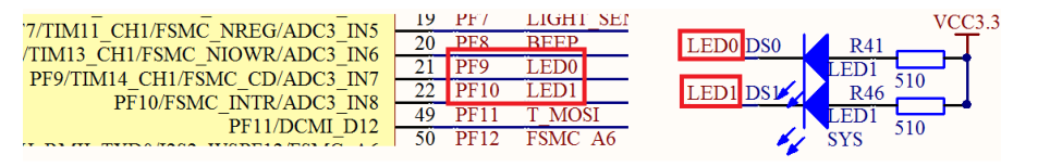
硬件只有 LED(DS0 和 DS1)。其电路在 ALIENTEK 探索者 STM32F4 开发板上默认是已经连接好了的。DS0 接 PF9,DS1 接 PF10。
对应的引脚为低电平的时候LED就亮,否则LED就灭。
03. 程序示例一
所有LED灭
- int main(void)
- {
- GPIO_InitTypeDef gpio_InitTypeDef;
-
- gpio_InitTypeDef.GPIO_Pin = GPIO_Pin_9 | GPIO_Pin_10;
- gpio_InitTypeDef.GPIO_Mode = GPIO_Mode_OUT;
- gpio_InitTypeDef.GPIO_Speed = GPIO_Speed_100MHz;
- gpio_InitTypeDef.GPIO_OType = GPIO_OType_PP;
- gpio_InitTypeDef.GPIO_PuPd = GPIO_PuPd_UP;
-
-
- delay_init(168);
-
- //1. 初始化GPIO的时钟
- RCC_AHB1PeriphClockCmd(RCC_AHB1Periph_GPIOF, ENABLE);
-
- //2. 初始化GPIO
- GPIO_Init(GPIOF, &gpio_InitTypeDef);
-
- //3. 设置高电平
- GPIO_SetBits(GPIOF, GPIO_Pin_9 | GPIO_Pin_10);
- return 0;
- }
04. 程序示例二
所有的LED亮
- int main(void)
- {
- GPIO_InitTypeDef gpio_InitTypeDef;
-
- gpio_InitTypeDef.GPIO_Pin = GPIO_Pin_9 | GPIO_Pin_10;
- gpio_InitTypeDef.GPIO_Mode = GPIO_Mode_OUT;
- gpio_InitTypeDef.GPIO_Speed = GPIO_Speed_100MHz;
- gpio_InitTypeDef.GPIO_OType = GPIO_OType_PP;
- gpio_InitTypeDef.GPIO_PuPd = GPIO_PuPd_UP;
-
-
- delay_init(168);
-
- //1. 初始化GPIO的时钟
- RCC_AHB1PeriphClockCmd(RCC_AHB1Periph_GPIOF, ENABLE);
-
- //2. 初始化GPIO
- GPIO_Init(GPIOF, &gpio_InitTypeDef);
-
- //3. 设置低电平
- //GPIO_ResetBits(GPIOF, GPIO_Pin_9 | GPIO_Pin_10);
- return 0;
- }
05. 程序示例三
LED闪烁
- #include "stm32f4xx.h"
- #include "delay.h"
- int main(void)
- {
- GPIO_InitTypeDef gpio_InitTypeDef;
-
- gpio_InitTypeDef.GPIO_Pin = GPIO_Pin_9 | GPIO_Pin_10;
- gpio_InitTypeDef.GPIO_Mode = GPIO_Mode_OUT;
- gpio_InitTypeDef.GPIO_Speed = GPIO_Speed_100MHz;
- gpio_InitTypeDef.GPIO_OType = GPIO_OType_PP;
- gpio_InitTypeDef.GPIO_PuPd = GPIO_PuPd_UP;
-
-
- delay_init(168);
-
- //1. 初始化GPIO的时钟
- RCC_AHB1PeriphClockCmd(RCC_AHB1Periph_GPIOF, ENABLE);
-
- //2. 初始化GPIO
- GPIO_Init(GPIOF, &gpio_InitTypeDef);
-
- //3. LED闪烁
- while(1)
- {
- //灭
- GPIO_SetBits(GPIOF, GPIO_Pin_9 | GPIO_Pin_10);
- delay_ms(1000);
-
- //亮
- GPIO_ResetBits(GPIOF, GPIO_Pin_9 | GPIO_Pin_10);
- delay_ms(1000);
- }
-
-
- return 0;
- }
|
.png) STMCU小助手
发布时间:2022-4-3 15:00
STMCU小助手
发布时间:2022-4-3 15:00
 微信公众号
微信公众号
 手机版
手机版