CAN控制器通过两根线上的电位差来判断总线电平
can.h
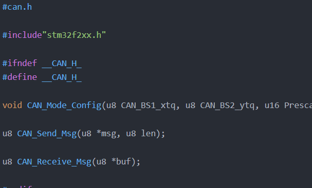
- #can.h
- #include"stm32f2xx.h"
- #ifndef __CAN_H_
- #define __CAN_H_
- void CAN_Mode_Config(u8 CAN_BS1_xtq, u8 CAN_BS2_ytq, u16 Prescaler);
- u8 CAN_Send_Msg(u8 *msg, u8 len);
- u8 CAN_Receive_Msg(u8 *buf);
- #endif
can.c
- #include"stm32f2xx.h"
- #include"stm32f2xx_can.h"
- #include"can.h"
- void CAN_Mode_Config(u8 CAN_BS1_xtq, u8 CAN_BS2_ytq, u16 Prescaler)
- {
- GPIO_InitTypeDef GPIO_InitStructure;
- CAN_InitTypeDef CAN_InitStructure;
- CAN_FilterInitTypeDef CAN_FilterInitStructure;
- NVIC_InitTypeDef NVIC_InitStructure;
- RCC_AHB1PeriphClockCmd(RCC_AHB1Periph_GPIOD, ENABLE); //使能AHB1外设时钟
- RCC_APB1PeriphClockCmd(RCC_APB1Periph_CAN1, ENABLE); //使能CAN1时钟
- //GPIO初始化
- GPIO_InitStructure.GPIO_Pin = GPIO_Pin_0|GPIO_Pin_1;
- GPIO_InitStructure.GPIO_Mode = GPIO_Mode_AF;
- GPIO_InitStructure.GPIO_OType = GPIO_OType_PP;
- GPIO_InitStructure.GPIO_Speed = GPIO_Speed_100MHz;
- GPIO_InitStructure.GPIO_PuPd = GPIO_PuPd_UP;
- GPIO_Init(GPIOD, &GPIO_InitStructure);
- GPIO_PinAFConfig(GPIOD, GPIO_PinSource0, GPIO_AF_CAN1);
- GPIO_PinAFConfig(GPIOD, GPIO_PinSource1, GPIO_AF_CAN1);
-
- //CAN初始化
- CAN_InitStructure.CAN_ABOM = DISABLE; //软件自动离线管理
- CAN_InitStructure.CAN_AWUM = DISABLE; //睡眠模式通过软件唤醒(清除CAN->MCR的SLEEP位)
- CAN_InitStructure.CAN_BS1 = CAN_BS1_xtq; //时间段1的时间单元,取值在CAN_BS1_1tq~CAN_BS1_16tq
- CAN_InitStructure.CAN_BS2 = CAN_BS2_ytq; //时间段2的时间单元,取值在CAN_BS2_1tq~CAN_BS2_8tq
- CAN_InitStructure.CAN_Mode = CAN_Mode_Normal; //模式设置,普通模式
- CAN_InitStructure.CAN_NART = ENABLE; //禁止报文自动传送
- CAN_InitStructure.CAN_Prescaler = Prescaler; //分频系数(Fdiv)为brp+1
- CAN_InitStructure.CAN_RFLM = DISABLE; //报文不锁定,新的覆盖旧的
- CAN_InitStructure.CAN_SJW = CAN_SJW_1tq; //重新同步跳跃时间单元,CAN_SJW_1tq~CAN_SJW_4tq
- CAN_InitStructure.CAN_TTCM = DISABLE; //非时间触发通信模式
- CAN_InitStructure.CAN_TXFP = DISABLE; //优先级由报文标识符决定
- CAN_Init(CAN1, &CAN_InitStructure);
- //筛选初始化
- CAN_FilterInitStructure.CAN_FilterActivation = ENABLE; 激活过滤器0
- CAN_FilterInitStructure.CAN_FilterFIFOAssignment = CAN_FilterFIFO0; //过滤器0关联到FIFO0
- CAN_FilterInitStructure.CAN_FilterIdHigh = 0x0000; //32位ID
- CAN_FilterInitStructure.CAN_FilterIdLow = 0x0000;
- CAN_FilterInitStructure.CAN_FilterMaskIdHigh = 0x0000; //32位MASK
- CAN_FilterInitStructure.CAN_FilterMaskIdLow = 0x0000;
- CAN_FilterInitStructure.CAN_FilterMode = CAN_FilterMode_IdMask; //屏蔽模式
- CAN_FilterInitStructure.CAN_FilterNumber = 0; //过滤器0
- CAN_FilterInitStructure.CAN_FilterScale = CAN_FilterScale_32bit; //
- CAN_FilterInit(&CAN_FilterInitStructure);
- CAN_ITConfig(CAN1, CAN_IT_FMP0, ENABLE); //fifo0的中断
- NVIC_InitStructure.NVIC_IRQChannel = CAN1_TX_IRQn; //stm..xx.h,发送中断
- NVIC_InitStructure.NVIC_IRQChannelCmd = ENABLE;
- NVIC_InitStructure.NVIC_IRQChannelPreemptionPriority = 0x01;
- NVIC_InitStructure.NVIC_IRQChannelSubPriority = 0x01;
- NVIC_Init(&NVIC_InitStructure);
- }
- //开始发送
- u8 CAN_Send_Msg(u8 *msg, u8 len) //msg为数据,len为长度
- {
- u8 mbox; //邮箱
- u16 i = 0;
-
- CanTxMsg TXmessage; //can发送结构体
-
- TXmessage.DLC = len; //数据个数,不能超过8个
- TXmessage.ExtId = 0x12; //扩展标示符
- TXmessage.IDE = CAN_ID_STD; //帧类型是标准帧,与这里的标准标示符和扩展标示符无关
- //TXmessage.IDE = CAN_ID_EXT; //这里的帧类型也可以设置为扩展帧,在USB_CAN那里设置标准帧,传输记录中会有
- TXmessage.RTR = CAN_RTR_DATA; //...can.h,传送的是数据帧
- TXmessage.StdId = 0x12; //标准标示符
-
- for(i = 0; i < len; i++)
- {
- TXmessage.Data<i> = msg;
- </i>}
-
- mbox = CAN_Transmit(CAN1, &TXmessage); //返回当前邮箱
- while((CAN_TransmitStatus(CAN1, mbox) == CAN_TxStatus_Failed)&&(i < 0xFFF))
- {
- i++; //等待发送结束完成
- }
- if(i >= 0xFFF)
- {
- return 1;
- }
- return 0;
- }
- u8 CAN_Receive_Msg(u8 *buf)
- {
- CanRxMsg RXmessage; //can接收结构体
- u16 i = 0;
- while(CAN_MessagePending(CAN1, CAN_FIFO0) == 0) //查询接收状态位,看是否由信息(报文)到达
- {
- return 0; //没有接收到数据,直接退出,看CAN_FIFO0中是否有数据
- }
- CAN_Receive(CAN1, CAN_FIFO0, &RXmessage); //接收信息(报文),将CAN_FIFO0中的数据通过can1拷贝到RXmessage结构体中
-
- for(i = 0; i < RXmessage.DLC; i++)
- {
- buf<span style="font-style: italic;"><span style="font-style: normal;"> = RXmessage.Data</span><span style="font-style: normal;">;
- }
- return RXmessage.DLC;
- }</span></span>
led.h
- #include"stm32f2xx.h"
- #ifndef __LED_H
- #define __LED_H
- void LED_Init(void);
- void Delay(vu32 nCount);
- void CTL_LED(u8 LED_NUM, u8 OFF_ON);
-
- #endif
led.c
- #include"led.h"
- #include"stm32f2xx.h"
- void LED_Init(void)
- {
- GPIO_InitTypeDef GPIO_InitStructure;
-
- RCC_AHB1PeriphClockCmd(RCC_AHB1Periph_GPIOD, ENABLE);
- GPIO_InitStructure.GPIO_Pin = GPIO_Pin_12|GPIO_Pin_11;
- GPIO_InitStructure.GPIO_Mode = GPIO_Mode_OUT; //led灯做输出,不用复用
- GPIO_InitStructure.GPIO_OType = GPIO_OType_PP; //GPIO_OType_PP表示推挽方式输出,GPIO_OType_OD表示开漏
- GPIO_InitStructure.GPIO_PuPd = GPIO_PuPd_UP;
- GPIO_InitStructure.GPIO_Speed = GPIO_Speed_50MHz;
- GPIO_Init(GPIOD, &GPIO_InitStructure);
- GPIO_SetBits(GPIOD, GPIO_Pin_12|GPIO_Pin_11);
- }
- void Delay(vu32 nCount)
- {
- for(; nCount != 0; nCount--);
- }
- #if 1
- void CTL_LED(u8 LED_NUM, u8 OFF_ON)
- {
- switch(LED_NUM)
- {
- case 0:
- if(OFF_ON == 1)
- {
- GPIO_ResetBits(GPIOD, GPIO_Pin_11);
- }
- else
- {
- GPIO_SetBits(GPIOD, GPIO_Pin_11);
- }
- break;
-
- case 1:
- if(OFF_ON == 1)
- {
- GPIO_ResetBits(GPIOD, GPIO_Pin_12);
- }
- else
- {
- GPIO_SetBits(GPIOD, GPIO_Pin_12);
- }
- break;
- default:
- //GPIO_ResetBits(GPIOF,GPIO_Pin_7|GPIO_Pin_8|GPIO_Pin_9|GPIO_Pin_10);
- GPIO_SetBits(GPIOD,GPIO_Pin_11|GPIO_Pin_12);
- break;
- }
- }
- #endif
main.c
- #include"stm32f2xx.h"
- #include"can.h"
- #include"led.h"
- int main(void)
- {
- u8 res;
- u8 key;
-
- u8 canbuf[8] = {0}; //这里因为不知道从USB_CAN发的是什么,只需初始化为0即可
- u8 a[8] = {02, 02, 02, 02, 02, 02, 02, 02}; //这里的02和2一样,12是0c
- LED_Init();
- Delay(168);
- CAN_Mode_Config(CAN_BS1_8tq, CAN_BS2_6tq, 8); //此时CAN波特率为:30000/(1+8+6)*8 = 250kbps
- while(1)
- {
- //1.接收数据
- key = CAN_Receive_Msg(canbuf);
- //2.解析数据
- if(key == 0)
- {
- CTL_LED(1, 0); //开始的时候,没有接收到数据,故左边灯亮
- }
- else if(key > 0) //当接收到数据时,开始执行这一步
- {
- //3.发送数据给PC
- CTL_LED(1, 1);
- res = CAN_Send_Msg(a, 8);
- if(res == 0)
- {
- CTL_LED(0, 1); //若数据发送成功,点亮led灯0
- }
- else
- {
- CTL_LED(1, 0); //若数据发送失败,熄灭led灯1
-
- }
- }
- }
- //开始的时候,没有接收到数据,故左边灯亮,当接收到数据时,开始执行发送数据函数,若发送成功,右边灯亮,
- //若数据发送失败,熄灭led灯1
- //问题:数据发送成功和失败的判断:是否合理?左边的灯会一直亮
- //结合上面程序,将没有接收到数据时灯灭,数据发送时灯亮,可知数据发送成功,
- //问题:can程序实验代码不显示接收?而且和发送数据框的数据无关?
- /*
- while(1)
- {
- res = CAN_Send_Msg(a, 8);
- if(res == 0)
- {
- CTL_LED(0, 1); //若数据发送成功,点亮led灯0,即右边灯
- key = CAN_Receive_Msg(canbuf);
- if(key == 0)
- {
- CTL_LED(1, 1); //实验结果是,执行这一步
- }
- else if(key > 0)
- {
- Delay(5000);
- //CTL_LED(1, 1); //灯1为左边的灯
- }
- }
- else
- {
- Delay(5000);
- //CTL_LED(1, 0); //若数据发送失败,点亮led灯1
- }
- }
- */
- }
|
.png) STMCU小助手
发布时间:2021-12-4 20:04
STMCU小助手
发布时间:2021-12-4 20:04
 微信公众号
微信公众号
 手机版
手机版