LED
注意GPIO口的初始化 C口对应8——15Pin
锁存器:GPIOD_Pin_2
初始化函数后应使用LED_Control(0xff,0)配置led
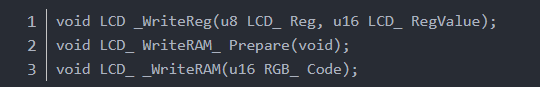
LCD和LED冲突解决方案
- <font face="微软雅黑" size="3">void LCD _WriteReg(u8 LCD_ Reg, u16 LCD_ RegValue);
- void LCD_ WriteRAM_ Prepare(void);
- void LCD_ _WriteRAM(u16 RGB_ Code);</font>
结尾添加: GPIOC->ODR = pcout;
如果要用LED_Contronl()进行多次位移操作需要四次初始化
4*8 = 32位寄存器
记得改写lcd.c
u16 pcout = GPIOC->ODR;
GPIOC->GPIOC = pcout;
LED_Control()
当led_status!=0时 置位 R S R GPIO:C D D Pin led_ctrl<<8 2 2
led_status==0时 置位 S S R GPIO:C D D Pin led_ctrl<<8 2 2
led.h
对led.c的初始化函数和调用函数进行声明
Key
初始化两个GPIO A B
GPIOA对应Pin 0 8
GPIOB对应Pin 1 2
三行代码消抖法
- <font face="微软雅黑" size="3">void Key_Read()
- {
- unsigned char ReadData = (KEYPORT)^0xff;
- Trg=ReadData & (ReadData ^ Cont);
- Cont=ReadData;
- }
- Trg 0x01 0x02 0x04 0x08对应RBT6平台的1——4独立按键
- </font>
key.h
#define KB1 GPIO_ReadInputDataBit(GPIOA,GPIO_Pin_0)
#define KB2 GPIO_ReadInputDataBit(GPIOA,GPIO_Pin_8)
#define KB3 GPIO_ReadInputDataBit(GPIOB,GPIO_Pin_1)
#define KB4 GPIO_ReadInputDataBit(GPIOB,GPIO_Pin_2)
#define KEYPORT KB1|(KB2<<1)|(KB3<<2)|(KB4<<3)|0xf0
编写范围变化的函数应该注意范围变动的逻辑可行性例如最高电压和最低电压 最高液面和最低液面
读值函数
GPIO_ReadInputDataBit()
TIM4
RCC_APB1PeriphClockCmd(RCC_APB1Periph_TIM4,ENABLE); //使能时钟
NVIC第一句配置需要注意改为TIM4
中断函数里注意使用静态变量
- <font face="微软雅黑" size="3">void TIM4_Init(void)
- {
- TIM_TimeBaseInitTypeDef TIM_TimeBaseStructure;
-
- NVIC_InitTypeDef NVIC_InitStructure;
-
- NVIC_InitStructure.NVIC_IRQChannel = TIM4_IRQn;
- NVIC_InitStructure.NVIC_IRQChannelPreemptionPriority = 0;
- NVIC_InitStructure.NVIC_IRQChannelSubPriority = 1;
- NVIC_InitStructure.NVIC_IRQChannelCmd = ENABLE;
-
- NVIC_Init(&NVIC_InitStructure);
-
- RCC_APB1PeriphClockCmd(RCC_APB1Periph_TIM4,ENABLE);
-
- TIM_TimeBaseStructure.TIM_Period = 1000-1;
- TIM_TimeBaseStructure.TIM_Prescaler = 71;
- TIM_TimeBaseStructure.TIM_ClockDivision = 0 ;
- TIM_TimeBaseStructure.TIM_CounterMode = TIM_CounterMode_Up;
-
- TIM_TimeBaseInit(TIM4,&TIM_TimeBaseStructure);
-
- TIM_ITConfig(TIM4,TIM_IT_Update,ENABLE);
-
- TIM_Cmd(TIM4,ENABLE);
- }
- </font>
ADC
ADC GPIO结构体初始化 RCC时钟使能 APB2 ADC1 APB2 GPIOB ENABLE
初始化通道8 ADC_Channel8_Init()
对应的GPIO口 GPIOB
对应的Pin口 Pin_0
adc_value=ADC_GetConversionValue (ADC1)读值函数
- <font face="微软雅黑" size="3">void ADC_Channel8_Init()
- {
- ADC_InitTypeDef ADC_InitStructure;
- GPIO_InitTypeDef GPIO_InitStructure;
-
- RCC_APB2PeriphClockCmd(RCC_APB2Periph_ADC1 | RCC_APB2Periph_GPIOC, ENABLE);
-
- GPIO_InitStructure.GPIO_Pin = GPIO_Pin_0;
- GPIO_InitStructure.GPIO_Mode = GPIO_Mode_AIN;
- GPIO_Init(GPIOB, &GPIO_InitStructure);
-
- ADC_InitStructure.ADC_Mode = ADC_Mode_Independent;
- ADC_InitStructure.ADC_ScanConvMode = ENABLE;
- ADC_InitStructure.ADC_ContinuousConvMode = ENABLE;
- ADC_InitStructure.ADC_ExternalTrigConv = ADC_ExternalTrigConv_None;
- ADC_InitStructure.ADC_DataAlign = ADC_DataAlign_Right;
- ADC_InitStructure.ADC_NbrOfChannel = 1;
- ADC_Init(ADC1, &ADC_InitStructure);
-
- /* ADC1 regular channel14 configuration */
- ADC_RegularChannelConfig(ADC1, ADC_Channel_8, 1, ADC_SampleTime_55Cycles5);
- /* Enable ADC1 DMA */
- ADC_DMACmd(ADC1, ENABLE);
-
- /* Enable ADC1 */
- ADC_Cmd(ADC1, ENABLE);
- /* Enable ADC1 reset calibration register */
- ADC_ResetCalibration(ADC1);
- /* Check the end of ADC1 reset calibration register */
- while(ADC_GetResetCalibrationStatus(ADC1));
- /* Start ADC1 calibration */
- ADC_StartCalibration(ADC1);
- /* Check the end of ADC1 calibration */
- while(ADC_GetCalibrationStatus(ADC1));
-
- /* Start ADC1 Software Conversion */
- ADC_SoftwareStartConvCmd(ADC1, ENABLE);
- }
- </font>
i2c
编写 写入和读取函数
- <font face="微软雅黑" size="3">//需要自己写的程序,读写AT24C02
- void Write_AT24c02(unsigned char add,unsigned char data1)
- {
- I2CStart();
- I2CSendByte(0xa0);
- I2CWaitAck();
- I2CSendByte(add);
- I2CWaitAck();
- I2CSendByte(data1);
- I2CWaitAck();
- I2CStop();
- }
- unsigned char Read_AT24c02(unsigned char add)
- {
- unsigned char temp;
- I2CStart();
- I2CSendByte(0xa0);
- I2CWaitAck();
- I2CSendByte(add);
- I2CWaitAck();
- I2CStart();
- I2CSendByte(0xa1);
- I2CWaitAck();
- temp=I2CReceiveByte();
- I2CWaitAck();
- I2CStop();
- return temp;
- }
- </font>
注意在i2c.h中声明新编写的函数
写入函数
- <font face="微软雅黑" size="3">Write_AT24c02(0x00,lcd_number /256);
- Delay_Ms(5);
- Write_AT24c02(0x01,lcd_number %256);
- Delay_Ms(5);</font>
lcd_record = Read_AT24c02 (0x00)*256 +Read_AT24c02 (0x01);
RTC
调整函数Time_Adjust()
RTC显示可以通过对THH,TMM,TSS赋值使得显示的初始值为期望值
如果出现59—>01的情况 则需要将rtc.c中的Time_Display(u32int TimeVar)中的
if(RTC_GetCounter()==0x0001517f)改为if(RTC_GetCounter()==0x00015180)
NVIC_InitStructure.NVIC_IRQChannelPreemptionPriority = 0;
NVIC_InitStructure.NVIC_IRQChannelSubPriority = 1;
rtc.h中添加“stdio.h”方便.c文件中函数调用
中断函数结尾需要加上
RTC_WaitForLastTask();
当出现59->01时可能是因为晶振温度变化 可以改7f->80
LCD显示
调整颜色
- <font face="微软雅黑" size="3">LCD_Clear(Blue);//清屏颜色
- LCD_SetBackColor(Blue);//背景颜色
- LCD_SetTextColor(White);//文本颜色</font>
- <font face="微软雅黑" size="3">LCD_SetTextColor(Red);
- LCD_DisplayChar(Line5,319-8*16,RTC_THH/10+'0');
- LCD_DisplayChar(Line5,319-9*16,RTC_THH%10+'0');
- LCD_SetTextColor(White);
- </font>
void STM_EVAL_COMInit( USART_InitTypeDef* USART_InitStruct);
void USART2_Init(void);
需要注意函数STM_EVAL_COMInit( & USART_InitStructure);的位置
一定放在USART_ITConfig(USART2, USART_IT_RXNE, ENABLE);的前面
int fputc(int ch,FILE *f)//需要包含stdio.h头文件
中断函数需要添加USART_ClearITPendingBit(USART2, USART_IT_RXNE);
- <font face="微软雅黑" size="3">void STM_EVAL_COMInit(USART_InitTypeDef* USART_InitStruct)
- {
-
- GPIO_InitTypeDef GPIO_InitStructure;
- /* Enable GPIO clock */
- RCC_APB2PeriphClockCmd(RCC_APB2Periph_GPIOA | RCC_APB2Periph_AFIO, ENABLE);
- RCC_APB1PeriphClockCmd(RCC_APB1Periph_USART2, ENABLE);
- /* Configure USART Tx as alternate function push-pull */
- // GPIO_InitStructure.GPIO_Mode = GPIO_Mode_AF_PP;
- // GPIO_InitStructure.GPIO_Pin = GPIO_Pin_2;
- // GPIO_InitStructure.GPIO_Speed = GPIO_Speed_50MHz;
- // GPIO_Init(GPIOA, &GPIO_InitStructure);
- /* Configure USART Rx as input floating */
- GPIO_InitStructure.GPIO_Mode = GPIO_Mode_IN_FLOATING;
- GPIO_InitStructure.GPIO_Pin = GPIO_Pin_2 | GPIO_Pin_3;
- GPIO_Init(GPIOA, &GPIO_InitStructure);
- /* USART configuration */
- USART_Init(USART2, USART_InitStruct);
-
- /* Enable USART */
- USART_Cmd(USART2, ENABLE);
- }
- void USART2_Init(void)
- {
- USART_InitTypeDef USART_InitStructure;
- NVIC_InitTypeDef NVIC_InitStructure;
- /* USARTx configured as follow:
- - BaudRate = 115200 baud
- - Word Length = 8 Bits
- - One Stop Bit
- - No parity
- - Hardware flow control disabled (RTS and CTS signals)
- - Receive and transmit enabled
- */
- USART_InitStructure.USART_BaudRate = 9600;
- USART_InitStructure.USART_WordLength = USART_WordLength_8b;
- USART_InitStructure.USART_StopBits = USART_StopBits_1;
- USART_InitStructure.USART_Parity = USART_Parity_No;
- USART_InitStructure.USART_HardwareFlowControl = USART_HardwareFlowControl_None;
- USART_InitStructure.USART_Mode = USART_Mode_Tx | USART_Mode_Rx;
- STM_EVAL_COMInit(&USART_InitStructure);
-
- /* Enable the USARTz Interrupt */
- NVIC_InitStructure.NVIC_IRQChannel = USART2_IRQn;
- NVIC_InitStructure.NVIC_IRQChannelPreemptionPriority = 0;
- NVIC_InitStructure.NVIC_IRQChannelSubPriority = 0;
- NVIC_InitStructure.NVIC_IRQChannelCmd = ENABLE;
- NVIC_Init(&NVIC_InitStructure);
-
- /* Enable the USARTz Receive Interrupt */
- USART_ITConfig(USART2, USART_IT_RXNE, ENABLE);
- }
- void SendString(char *s)
- {
- while(*s)
- {
- USART_SendData(USART2,*s++);
- /* Loop until the end of transmission */
- while (USART_GetFlagStatus(USART2, USART_FLAG_TXE) == RESET)//USART_FLAG_TC 表示传输完毕;USART_FLAG_TXE表示发送缓冲区空
- {}
- }
- }
- /**
- * @brief Retargets the C library printf function to the USART.
- * @param None
- * @retval None
- */
- int fputc(int ch, FILE *f)
- {
- /* Place your implementation of fputc here */
- /* e.g. write a character to the USART */
- USART_SendData(USART2, (uint8_t) ch);
- /* Loop until the end of transmission */
- while (USART_GetFlagStatus(USART2, USART_FLAG_TXE) == RESET)
- {}
- return ch;
- }
- u8 rx_buf[15];
- u8 rx_count=0;
- u8 rx_ideltime=0;
- _Bool rx_flag=0;
- void USART2_IRQHandler(void)
- {
- if(USART_GetITStatus(USART2, USART_IT_RXNE) != RESET)
- {
- USART_ClearITPendingBit(USART2,USART_IT_RXNE);
- rx_buf[rx_count]=USART_ReceiveData(USART2);
- if(rx_buf[rx_count]=='\n')
- {
- rx_flag=1;
- rx_count=0;
- }
- rx_count++;
- rx_ideltime=0;
- }
- }
- </font>
时钟频率(system clk) / 预分频(psc) /想要的pwm频率 = arr(重装值)
通过输出比较模式进行占空比调节
- <font face="微软雅黑" size="3">__IO uint16_t TIM2_CCR2_Val = 8192;
- __IO uint16_t TIM2_CCR3_Val = 4096;
- void TIM2_PWM_OCToggle(void)
- {
- NVIC_InitTypeDef NVIC_InitStructure;
- TIM_TimeBaseInitTypeDef TIM_TimeBaseStructure;
- TIM_OCInitTypeDef TIM_OCInitStructure;
- GPIO_InitTypeDef GPIO_InitStructure;
- uint16_t PrescalerValue = 0;
- /* System Clocks Configuration */
- /* TIM2 clock enable */
- RCC_APB1PeriphClockCmd(RCC_APB1Periph_TIM2, ENABLE);
- /* GPIOA clock enable */
- RCC_APB2PeriphClockCmd(RCC_APB2Periph_GPIOA | RCC_APB2Periph_GPIOB|
- RCC_APB2Periph_GPIOC | RCC_APB2Periph_AFIO, ENABLE);
- /* NVIC Configuration */
- /* Enable the TIM2 global Interrupt */
- NVIC_InitStructure.NVIC_IRQChannel = TIM2_IRQn;
- NVIC_InitStructure.NVIC_IRQChannelPreemptionPriority = 0;
- NVIC_InitStructure.NVIC_IRQChannelSubPriority = 1;
- NVIC_InitStructure.NVIC_IRQChannelCmd = ENABLE;
- NVIC_Init(&NVIC_InitStructure);
- /* GPIO Configuration */
- GPIO_InitStructure.GPIO_Pin = GPIO_Pin_1 | GPIO_Pin_2;
- GPIO_InitStructure.GPIO_Mode = GPIO_Mode_AF_PP;
- GPIO_InitStructure.GPIO_Speed = GPIO_Speed_50MHz;
- GPIO_Init(GPIOA, &GPIO_InitStructure);
- /* ---------------------------------------------------------------------------
- TIM2 Configuration: Output Compare Toggle Mode:
- TIM2CLK = SystemCoreClock / 2,
- The objective is to get TIM2 counter clock at 12 MHz:
- - Prescaler = (TIM2CLK / TIM2 counter clock) - 1
- CC1 update rate = TIM2 counter clock / CCR1_Val = 366.2 Hz
- CC2 update rate = TIM2 counter clock / CCR2_Val = 732.4 Hz
- CC3 update rate = TIM2 counter clock / CCR3_Val = 1464.8 Hz
- CC4 update rate = TIM2 counter clock / CCR4_Val = 2929.6 Hz
- ----------------------------------------------------------------------------*/
- /* Compute the prescaler value */
- PrescalerValue = (uint16_t) (SystemCoreClock / 24000000) - 1;
- /* Time base configuration */
- TIM_TimeBaseStructure.TIM_Period = 65535;
- TIM_TimeBaseStructure.TIM_Prescaler = PrescalerValue;
- TIM_TimeBaseStructure.TIM_ClockDivision = 0;
- TIM_TimeBaseStructure.TIM_CounterMode = TIM_CounterMode_Up;
- TIM_TimeBaseInit(TIM2, &TIM_TimeBaseStructure);
- /* Output Compare Toggle Mode configuration: Channel2 */
- TIM_OCInitStructure.TIM_OCMode = TIM_OCMode_Toggle;
- TIM_OCInitStructure.TIM_OutputState = TIM_OutputState_Enable;
- TIM_OCInitStructure.TIM_Pulse = TIM2_CCR2_Val;
- TIM_OCInitStructure.TIM_OCPolarity = TIM_OCPolarity_Low;
- TIM_OC2Init(TIM2, &TIM_OCInitStructure);
- TIM_OC2PreloadConfig(TIM2, TIM_OCPreload_Disable);
- /* Output Compare Toggle Mode configuration: Channel3 */
- TIM_OCInitStructure.TIM_OutputState = TIM_OutputState_Enable;
- TIM_OCInitStructure.TIM_Pulse = TIM2_CCR3_Val;
- TIM_OC3Init(TIM2, &TIM_OCInitStructure);
- TIM_OC3PreloadConfig(TIM2, TIM_OCPreload_Disable);
- /* TIM enable counter */
- TIM_Cmd(TIM2, ENABLE);
-
- /* TIM IT enable */
- TIM_ITConfig(TIM2, TIM_IT_CC2 | TIM_IT_CC3 , ENABLE);
- }
- uint16_t TIM2_capture = 0;
- _Bool TIM2_CH2_flag=0, TIM2_CH3_flag=0;
- float TIM2_CH2_duty=0.3, TIM2_CH3_duty=0.7;
- void TIM2_IRQHandler(void)
- {
- /* TIM2_CH2 toggling with frequency = 732.4 Hz */
- if (TIM_GetITStatus(TIM2, TIM_IT_CC2) != RESET)
- {
- TIM_ClearITPendingBit(TIM2, TIM_IT_CC2 );
- TIM2_capture = TIM_GetCapture2(TIM2);
- if(TIM2_CH2_flag==1)
- {
- TIM_SetCompare2(TIM2, TIM2_capture + (u16)(TIM2_CCR2_Val*TIM2_CH2_duty));
- TIM2_CH2_flag=0;
- }
- else
- {
- TIM_SetCompare2(TIM2, TIM2_capture + (u16)(TIM2_CCR2_Val*(1-TIM2_CH2_duty)));
- TIM2_CH2_flag=1;
- }
- }
- /* TIM2_CH3 toggling with frequency = 1464.8 Hz */
- if (TIM_GetITStatus(TIM2, TIM_IT_CC3) != RESET)
- {
- TIM_ClearITPendingBit(TIM2, TIM_IT_CC3);
- TIM2_capture = TIM_GetCapture3(TIM2);
- if(TIM2_CH3_flag==1)
- {
- TIM_SetCompare3(TIM2, TIM2_capture + (u16)(TIM2_CCR3_Val*TIM2_CH3_duty));
- TIM2_CH3_flag=0;
- }
- else
- {
- TIM_SetCompare3(TIM2, TIM2_capture + (u16)(TIM2_CCR3_Val*(1-TIM2_CH3_duty)));
- TIM2_CH3_flag=1;
- }
- }
- }
- </font>
检查microusb的选项是否勾选
|
.png) STMCU小助手
发布时间:2021-8-10 13:58
STMCU小助手
发布时间:2021-8-10 13:58
 微信公众号
微信公众号
 手机版
手机版