.png) andey
发布时间:2025-2-23 20:04
andey
发布时间:2025-2-23 20:04
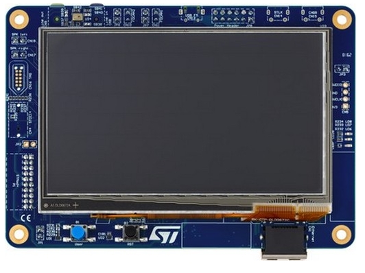
简介感谢社区的GUIdemo 活动的开发板,本次申请的板卡为STM32H745I-DISCO 开发板,本次活动计划首先搭建基础开发工程(添加Uart 输出log用于调试,使用freertos),移植适配LVGL,基于LVGL创建仪表显示功能,我们先开始第一步的开发,搭建基础工程。 UART 的配置开发板上将UART3 连接至了STLINK的虚拟串口,我们可以使用此串口来打印调试信息,对应原理图如下。
根据上述原理图,使用CubeMx 创建工程配置,PB10,PB11为串口功能,对应配置如下。
UART 参数配置为115200 8N1,并开启中断。
参数配置OK 代码中添加 printf 重定向到uart3 的处理,在IAR 中对应的底层IO函数为__write 函数,简单的对接即可实现printf 函数打印输出至uart3的功能。 适配FreeRtosSTM32 的SDK 中默认把systick 用作HAL库的延时时间基础的timer,FreeRtos 中通常使用systick 来作为系统调度的定时器,这块需要修改下CubeMx 配置,配置TIM6作为HAL库使用的定时器。 CubeMx 使能TIM6
CubeMx SYS timer 选择TIM6
开启FreeRTOS 组件
适配完成后,在生成的默认任务中添加之前适配好的uart printf 打印功能。 运行后,在任务内已经可以按照预期的输出打印了,至此GUI demo 的基础工程搭建基本完成,下一步开始LTDC 驱动适配来点亮 开发板的屏幕,为GUI Demo 应用LVGL 做好底层服务。
|
【逢7发帖赢大礼】#5 Arduino UNO Q的led matrix
【逢7发帖赢大礼】#4 使用Arduino APP LAB 玩arduino UNO Q
【逢7发帖赢大礼】STM32开发之WIFI实时时钟
【逢7发帖赢大礼】#3 STM32U新进驻的新开发板Arduino UNO Q
【 逢7发帖赢大礼】7、TouchGFX中实现云彩流动效果
【逢7发帖赢大礼】#2 STM32F429-Discovery在 Arduino 中的使用
【 逢7发帖赢大礼】6、TouchGFX中添加图像素材和自定义代码编辑
【 逢7发帖赢大礼】5、TouchGFX 创建自定义界面和交互
【 逢7发帖赢大礼】4、CubeMX工程复用以及TouchGFX应用
【 逢7发帖赢大礼】3、利用CubeMX添加TouchGFX功能:工程修改和编译烧录
 微信公众号
微信公众号
 手机版
手机版